
By Bradley Clark - images & text © 2002
|
Armorcast produces a wonderful model of the 75 ton omnimech Mad Cat (known as the Timber Wolf among the Clans). While the amount of resin makes this model durable enough for large scale Battletech and Mechwarrior gaming, like the small scale pewter versions the cockpit canopy is merely painted (usually a gray or metallic silver to represent the glass) which I found a shame. | |||
|
To do the detailing and "correcting" I have done requires
I then borrowed a friend's Dremal tool as my rotary tool does not have the attachable flexible shaft and cylindrical cutter bit, which is easier to handle than grinding out the resin with the bulk of the motor housing in hand. Starting at the back, hollow out the pircr. Try to keep the thickness of the half circle and follow the contour of the outside curvature. Use care around the canopy area especially the lower windows. It is best to do this in a room with a lamp nearby; pause now and again to hold the piece head-on before you and look at the window areas; the more light showing through the resin the thinner it is in that area. Once the canopy is letting the light show through all the windows put the piece down and from the center of the large windows drill through with the bit and slowly eat away to the edges of the window. The side ones are a bit tricky as you should keep the separation between the windows vertical but the bottom should be horizontal, just take it slow and all will be fine. The smaller windows just required me to drill carefully with the bit then file the corners out. Lastly file all the edges smooth. Trace as best you can the box outline of the cockpit you'll be installing (unless you got a cockpit with rounded sides to fit the contours of the fighter body then you should "square" it up first to fit). Position the cockpit on the top half of the head/center torso so the ejection seat will be below the engraved hatch, then trace the outline of the cockpit tub. Slowly grind out the resin, test fitting the cockpit intermittently for adjustments, until the side instrument panels are almost flush with the resin of the model. Glue the cockpit in place. Set the ejection seat, and pilot if you have one, in to check the clearance of the top head/center torso half; thinning as necessary back to just beyond where the hatch is on the outside. Once enough room has been established take a round smoothing bit and smooth the inside curve of the head/center torso being careful not to break the division between windows. Cut a few pieces (or one if your good enough and take time to measure) of thin styrene to cover any gaps between the cockpit and the model taking care to cut the pieces so the head/center torso doesn't sit on top of them making the gap between the halves bigger. |
||||
|
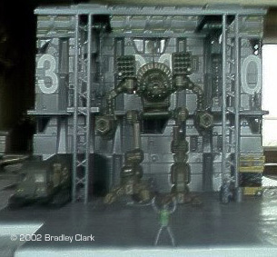
Image: The completed diorama |
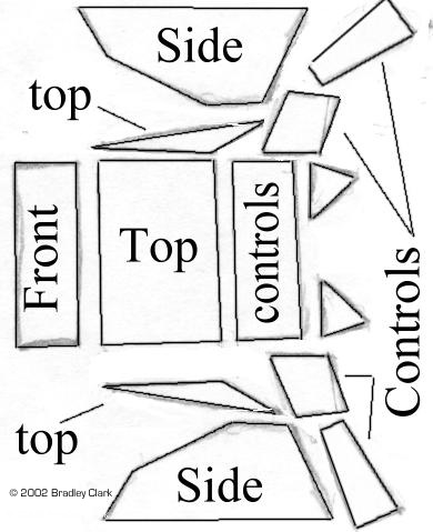
The forward heads-down display and instrument panel I made of sheet styrene, as the items provided with the fighter were round at the top. This drawing of the pieces I made is full-sized, but I think shrinking the dimensions a little would have been better. Some of the side pieces around the leg/pedal area are made through trial and error. An option here if your cockpit has a rounded top is to cut part of the fighter body from the cockpit area and glue that in place of the boxy construction, it’s your model. I didn’t paint the cockpit then add decals, it happened that I had ordered what I thought was an F-16 cockpit from Roll Models, but turns out they were placards for the instrument panels. I cut out the metal placards and superglued them on the styrene panels as I saw fit. I then cut out foil instrument panels that looked like they fit on the placards, super glued them on and then painted the interior Aged Metal (a water-based fantasy figure paint by Ral Partha). You can paint the cockpit immediately if you use decals and do not wish to buy placards, though the raised detail is great. For the ejection seat thin strips of masking tape make great seat belts and can be placed around the pilot for added realism. Once the cockpit is done to your liking hold a piece of paper inside the canopy area. Trace the windows onto the paper, then cut out the window pieces leaving some excess around the back and front. Use these as templates to cut the glass from the transparent sheets. Test fit each panel and see how well it comforms to the curve of the window, then carefully glue each in place holding it in for a bit with a finger so the glue holds it to the curving shape. If too much white develops at the edge or you the glue ruins the “clean glass”, pop it out with a finger and start anew. For the lower windows one strip can work for all three but may require a few attempts to avoid glue mess ups. Once the glue is cured, some gentle wiping with glass cleaner and q-tips (cotton buds) removes fingerprints. Paint the inside to match the cockpit. As a last touch a piece of styrene can be cut to fit in behind the cockpit and glued to the upper head/center torso half to avoid the hollow look. You can glue a ladder to the hatchway as well as trace the hatch and cut out a styrene hatch for the inside. Oh, don’t forget to drill and mount a short bent antenna in the round nub just before the body box. The other “corrections” are my personal preference. The metal missile warheads that come with the kit are just too large for the launchers to house twenty to a shot (or at least too large for the number of rounds stored in the torsos) so I left them off and painted the holes Burnt Iron. My bottle says "for airbrush" but does well enough brushed on and is thin enough that you can wipe accidents away (if anybody notices the darkening of paint around the holes it can be attributed to exhaust burn from launches). The metal miniature and most pictures I’ve seen have the body as being rounded rather than the square body box with the excess detail of the kit. To reflect this, I first sawed lines (shown in at left) to help judge how straight the diagonal cuts were. I then sawed off the edges and filed the curve to match the decoration on the front. Using the side of a straight needle file I marked the lines from the mini onto the newly rounded body box. Using the edge of the file's square tip I “carved” them in a bit (See the next to last picture at left). Lastly I drilled holes in all the pieces and glued wire pins into the launcher bodies for holding power and to keep from having to remove both arm and torso if I decide to change arm weapons. The stops on the back of the arm pod were removed and the pod glued level but allowed to swing left/right. Lastly, I bit by bit removed the mounts for the metal hoses on the backs of the legs (don’t know why they’re there anyway - one good shot and ...). Should you want to get away from the powered down look that the mech is designed for, but think the one-foot-in-front-of-the-other look is too ordinary follow these steps: |
|
![]()
This page copyright © 2002 Starship Modeler™. Last updated on 9 August 2002.
 The first step is to purchase a cheap 1/48 fighter kit as I did. You could also choose a resin cockpit, which I am told provides more detail than mosy plastic kit cockpits but aren't cheap and may not have an ejection seat and/or pilot. Once you have the cockpit it is time to prepare the rounded head/center torso piece (see picture at left). As you will notice when you have the kit, this piece is a hollow half circle until just around the area of the hatch then it becomes solid resin.
  To install the cockpit first use a razor saw to cut off the "chin" as we'll call it. Begin by placing the saw under the lower edge of the three small windows; this edge will guide the saw somewhat and will align you with where the back part of the piece attaches to the lower body. Saw away just enough that you carve a line dividing the round head section in half all the way around to meet and merge with the edge of where the body attaches, Alternating among left, front and, right continue to saw along the line using it to be sure the cut is as level and straight as possible until the "chin" is separated (see picture at right). Using the top part to keep it level, superglue the "chin" to the lower body.
![[Click to enlarge]](bc_supercat_4.JPG)
![[Cockpit]](bc_supercat_5.JPG)
![[Click to enlarge]](bc_supercat_6.JPG)
![[Rounding off the corners, just like on the mini]](bc_supercat_7.JPG)
![[Scribing new lines based on the mini]](bc_supercat_8.JPG)
![[Click to enlarge]](bc_supercat_9.jpg)