
By Mark Crees - images & text © 1999
|
 You want lights in this kit. Ok. I've read reviews by other modellers on lighting the various Star Trek kits, and it has always seems to be a living nightmare. Wiring, running lights, cutting out windows. It looks daunting. Well, it sure felt daunting when I started out, but planning and a basic knowledge of electricity helps a lot. |
|
|
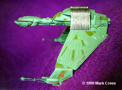
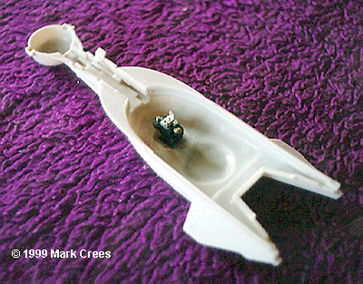
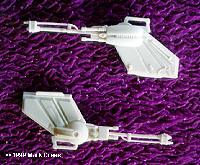
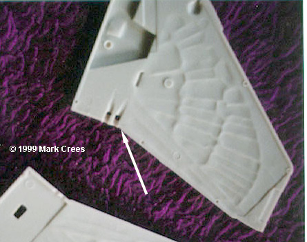
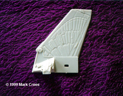
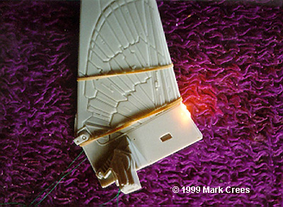
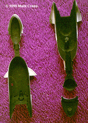
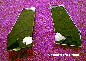
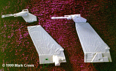
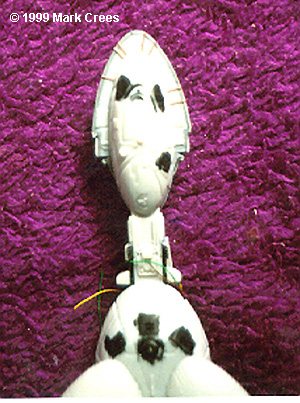
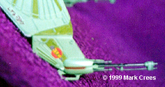
Opening the box you'll see: 6 Sprue trees and a few clear parts, a large instruction sheet, a small set of decals and a 2 piece flight display stand (this one was the Flight Display kit with clear plexiglass display stand). The first thing I noticed was how simple it was to build sub assemblies. I had to refrain from racing in an building the entire thing in 1 day. I planned to light this kit, so planning the placemnt and wiring of them was essential. Next how to power the lights. Ok, I don't know much about electronics, so I immediately shelved the idea of using LED's or fluorescent lights. Another Option was to run fibre optics. Unfortunately fibre optics don't come in wide narrow strands. Light sheet would work, but I would take ages to order (Australia doesn't have a dealer that I know of). I chose mini bulbs. The are small, require little or no electronic knowledge and easy to get. The mini bulbs require 12V power supply. You can pick these up at any electronic to hobby shop. The wings hold 2 light bulbs each, and I decided on 2 bulbs in the fuselage for lighting the windows. To attach the lights to the power supply, I brought a female plug socket (you can get 2 in a pack - spare for another project). I chose to mount the plug socket where the display stand would be inserted (this would not be needed since I was using the Flight Display stand). I drilled a hole in this area, the same size as the plug being inserted into the socket. I then glued the plug socket in place using super glue. The interior is wide open and has plenty of room for wiring. Next, I tackled the wings. They are basically 4 pieces each: a 2 piece wing and a 2 piece phaser. When looking at the wing, I noticed dimples near the wing roots (where the wing meets the fuselage) These represent the "landing" lights and are meant to be painted white. I replaced this by lights. I removed the dimples and started planning how much material to remove to fit the bulbs. I then carved channels into and behind where the dimples where located. I didn't worry about removal of the wing material as I could replace this later. I fitted the lights into the area frequently to ensure I didn't remove too much material. Once satisfied with this, I looks at where the wires needed to go (they have to be connected to the main power source) The reactor fins (refer to step 3 and 4) join both the wing and fuselage together and have a plenty of room to house the wiring. I cut out a rectangle in the middle of the area where the fins meet the wing, to allow the wiring to run into the wing from the fuselage. Next I had to find out what would happen to the wing when the lights were turned on. I placed the lights into the wing and ran the wires to a power supply. Holding the pieces together with rubber bands, I turned the power on. The result: a glowing model (or parts of it, anyway). Basically the area surrounding the lit bulbs glowed. To get around this problem, I had to make all areas of the model "light tight". I painted all areas with black matte paint (Testors Model Master). I then painted silver the fuselage interior and the areas of the wing that hold the lights. This reflects the light inside the ship. Once happy with the results (I had to check several times for glowing plastic) I glued the wings together as per instructions. I glued both phaser parts, but only glued 1 to its respective wing. The other had to remain free so it could be inserted into the flight display stand. Next, I chose which wing configuration to have. I chose to position the wing in attack mode. I glued these pieces together. These were dry fitted to both the wing and fuselage to see if there were any fit problems. I filled the gap that was present by gluing strips of plastic card in place and dry fitting to the wing and fuselage to make sure the gap went away. Once I was happy with this, I painted the reactor fins steel, weathered with a black wash and dry brushed with silver and put them aside till later. Next, I moved to the fuselage. I placed 1 bulb in the front of fuselage and 1 in the rear, and joined the wires to the power socket. Once again I tested the model for glowing plastic. I also cut the windows out of the fuselage. Once I was satisfied, I superglued the lights in place and ran extra wires to connect to the wires for the wings (these were connected after the painting stage). I then closed the fuselage halves and filled gaps with putty. Once everything was sanded back, the entire model was given an overcoat of black prior to painting. Painting was done as per instructions. Model Master paints were used everywhere. I airbrushed the base colors, then hand painted the other colors. This meant a long and laborious task. When done, I glued the reactor fins onto the wings and threaded the wire through the fins. These wires were the connected to the wires coming out of the fuselage. The wires were tucked into the reactor area and the complete wing and reactor fin glued to the fuselage and left to set. The entire model was overcoated with several applications of Model Master Gloss, prior to the decals being applied. I used Mr Mark Softener to soften the decals and white glue to make the adhere to the surface (AMT/ERTL decals don't react to the decal solution nor adhere to the decal surface without a little boost, I've found.) Once the decals were dry, the entire model received a Flat coat finish. The wing that doesn't have the phaser cannon connected was placed through the opening of the Flight Display Stand and the phaser cannon was connected to the wing (I didn't apply glue, since I wanted to move the model around). Overall I spent about 30 hours on the kit, mostly on the lighting and painting. It's a good model to add to that Star Trek Collection. Lighting this kit makes it stand out from the crowd, and it was not at all hard to do. Now to start on the other Star Trek kits - with lights..... |
![]()
This page copyright © 1997-9 Starship Modeler™. Last updated on 25 October 1999.
![[Parts, and lots of 'em]](mc_kbop19a.JPG)
![[Holes drilled for lights and wiring]](mc_kbop17.JPG)
![[Fuselage ready to go]](mc_kbop18a.JPG)
![[Wired and ready for paint]](mc_kbop21a.JPG)
![[Assembly]](mc_kbop23a.JPG)
![[Top, lighted]](mc_kbop3.JPG)
![[Front, lighted (click)]](mc_kbop2.jpg)
![[Underside]](mc_kbop6.jpg)
![[Top]](mc_kbop7.JPG)