
By Ivan Place, Jr. - images & text © 2003-2004
|
 |
|
I'm a straightforward person, so here's the deal: Nothing new in building this kit and my next one will be much better. The normal putty-sand-prime-putty-prime-sand method applies in doing away with the seam where the main hull meets the engine wing section. I used 400, 600, and 800 grit sandpaper and Testors red putty and Painters' Touch wet/dry sandable primer. Three white LED's were used to light the forward hull, and one for the main hull that is bright enough to light the after-market deflector dish. Each engine had one red and blue LED. I did not separate the bussard compartment LED because the blue light reflecting onto the red gives the 'watermelon pink' effect for the bussard area. Front and rear impulse engine areas were lit with a single red LED. I airbrushed the model the best I could with the paint scheme from original studio data with resources from SSM and other model sites. If I were an airbrush artist or Pro, it would be 'dead-on.' The whole project took no more than 30 hours spread over ten days. The most time consuming part was applying 95% of all those aftermarket decals! |
|
|
|
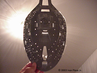
Days 1 and 2 Today the windows to be lit were drilled out. The hull is partially assembled and the pieces puttied, sanded, and primed. This was followed by the first coats of light-blocking paint. Image: A simple test to detect light leaks Image: Not all windows are to be lit - after all, the crew has to sleep sometime ... |
|
|
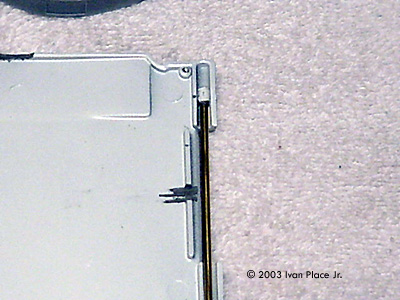
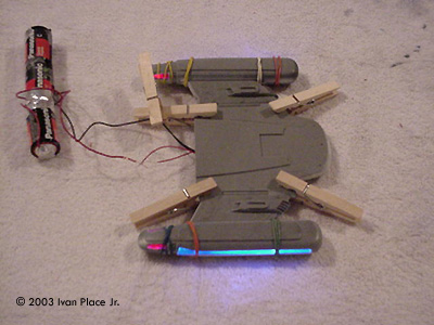
Days 3 and 4 The main parts were readied for light reflection using aluminum tape and white paint. Brass rods were installed in the "wings" for strength. The rear shuttle deck/warp pylons/warp engines were then assembled. The LED's were tested for several hours to see how long the batteries could be expected to last. Image: Warp engines being assembled Image: Light test |
|
Image: Warp engines in the "up" position |
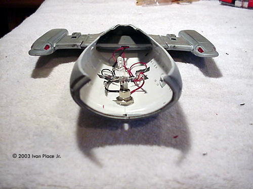
Days 5 and 6 Wiring was installed in the primary and secondary hulls and a female AC/DC adapter installed with solder. Loctite gel epoxy was used for added strength over the adapter and soldered connections. The "wings" were again tested for mobility before closing up the hull. |
| |
Days 7 and 8 Final priming and sanding were completed, followed by a wipe-down with a damp rag . Then the model was painted. |
|
|
Days 9 and 10 A clear gloss coat was applied and then the decals. Lots and lots of decals, from the kit and an aftermarket set. When those were all in place, the model received a final clear coat. Image: Bridge details |
|
This model looks much better in person than in the pics, but hey; maybe Santa will get me a new digital camera for Christmas. |
|
![]()
This page copyright © 2004 Starship Modeler™. First posted on 20 July 2004.
![[Click to enlarge]](ip_voy_05.JPG)
![[Click to enlarge]](ip_voy_A.JPG)
![[Click to enlarge]](ip_voy_D.JPG)
![[Click to enlarge]](ip_voy_H.JPG)
![[Click to enlarge]](ip_voy_K.JPG)
![[Click to enlarge]](ip_voy_L.JPG)