
|
By Tom Kowaliski - images & text © 2006
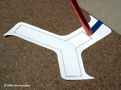
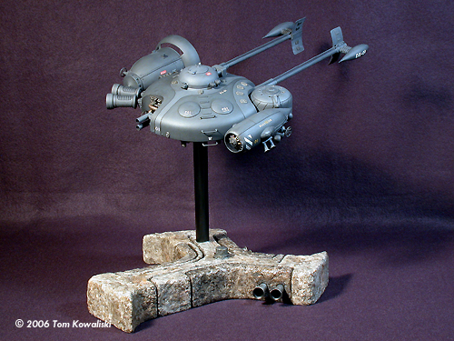
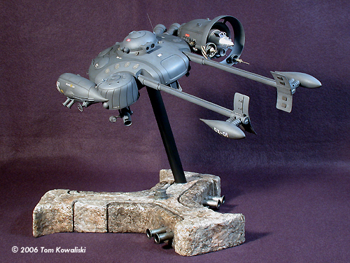
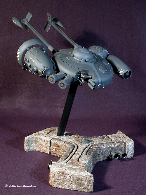
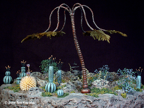
This particular display base, intended for my Blackwind project, is prime example of stonework made to order. It's a simple wood frame shaped to the modeler's needs, electrified, and then covered in whatever material you choose to simulate the rock. This is the first time I've photographed a project from start to finish so there's something new here for everybody. Part One: Wood It started with two sheets of half inch particle board laminated together. Actually it started months before that, drawing several different base designs for the Black Wind to roost on. I finally chose this three spoked pattern. I also chose an angled riser to allow an easier view of the models bottom detail. So I laid the cut out paper pattern on the particleboard and tried to determine where the model would center above the pattern. When the correct angle for the riser was determined, an adjustable guide was used to match that angle for drilling the holes. |
![[Please Click to enlarge]](bw_base/64TheFinishedBase.jpg) |
|
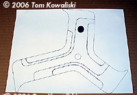
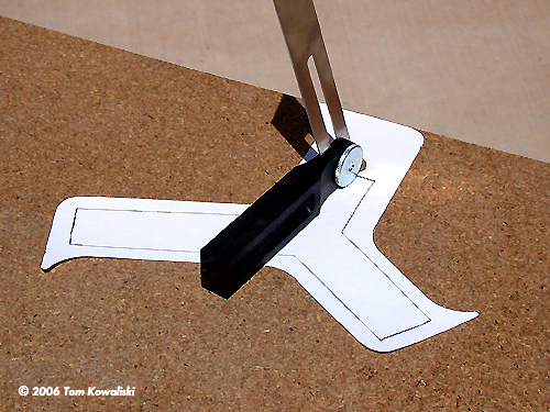
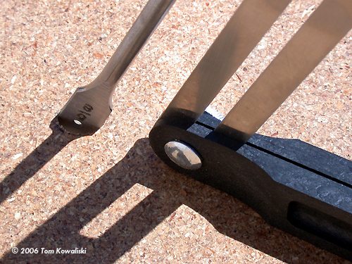
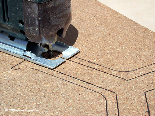
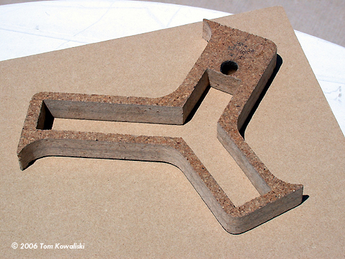
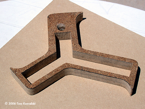
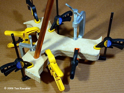
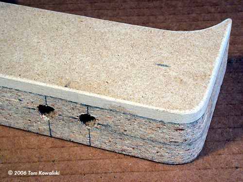
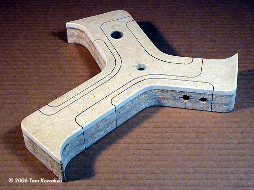
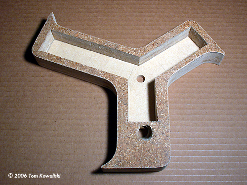
Image: Positioning the stand hole at the proper angle Image: Drilling at the correct angle Image: Riser and pattern in place Image: Pattern drawn on the board Image: Starter holes drilled Image: First the inside is cut out Image: Then the outside cuts are made and everything sanded smooth Image: The base is used to draw the pattern for the top plate Image: Top plate cut out Image: Thin but strong Image: Glued and clamped Image: Sanded and ready Image: Holes drilled for hot rod exhaust
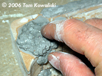
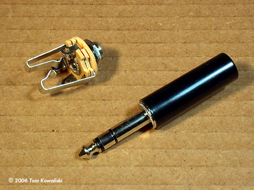
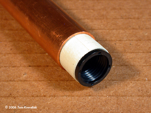
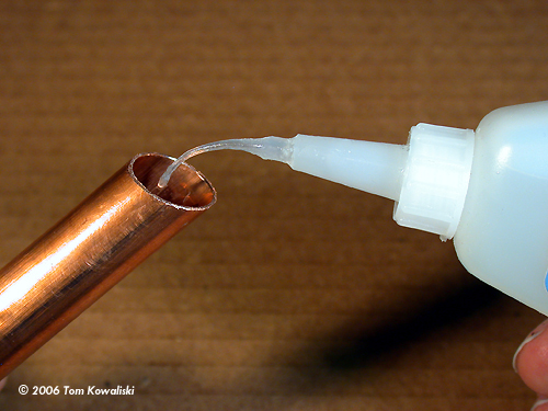
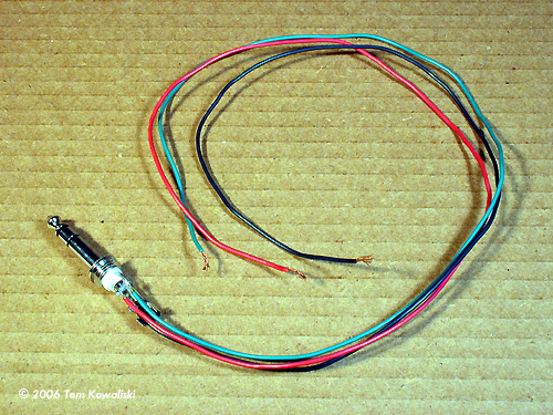
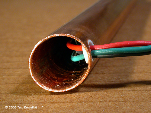
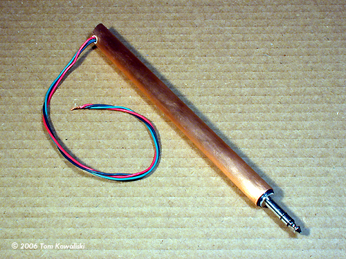
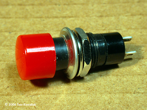
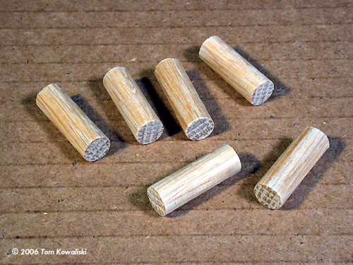
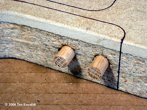
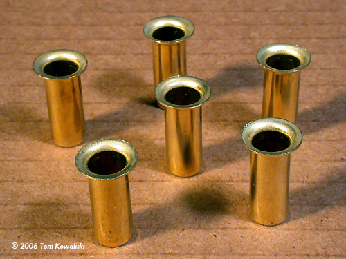
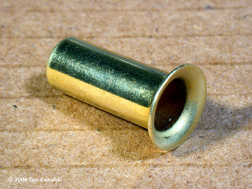
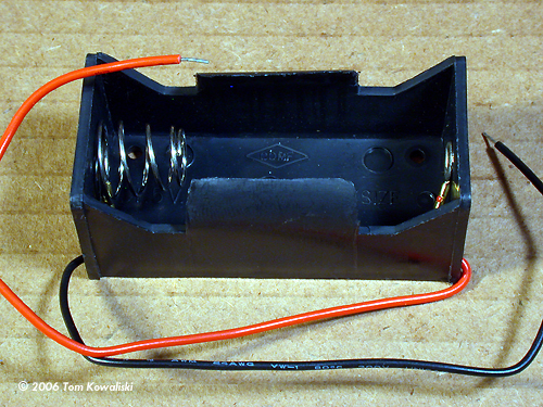
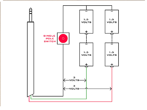
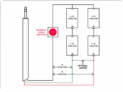
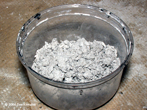
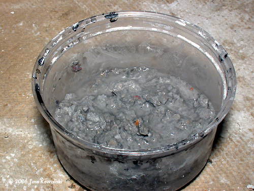
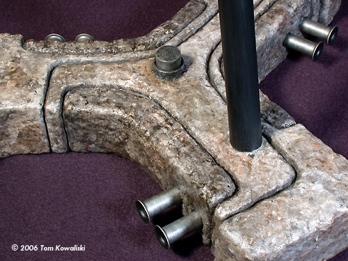
Image: Stonework pattern transferred to the base Image: Ready for wiring Image: Male and female stereo jacks Image: Strong rotating connection Image: Tape wrap ensures a snug fit Image: Insulator inserted Image: Ready for glue Image: Gravity does the work Image: Evergreen insulator Image: Wires soldered to the jack Image: Jack installed Image: Wires run through the insulator Image: Finished riser Image: Push button Image: Installed Image: Another look Image: Wooden doels to hold the exhaust pipes Image: Dowels in place Image: Flared pipes Image: It's a tubing sleeve Image: Test fit Image: Battery holder Image: Wires threaded along the side Image: Wiring finished and tested Image: Screws poked through Image: Painting the switch button Image: Turned to stone Image: Workings protected Image: Diagram: Dual Isolated Circuit Image: Diagram: Optional Jumper for single circuit Image: Insta-Rock Image: Put it in a bowl Image: Add water
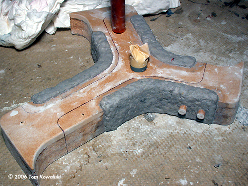
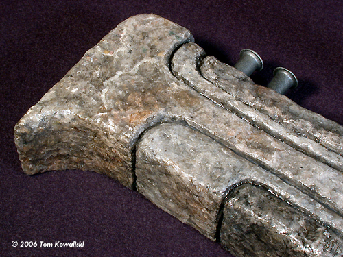
Image: First layers Image: Scribing Image: Let dry a day Image: Looking good Image: Superglue for strength Image: Sealing the whole base Image: Rock hard Image: Painting the pipes Image: Masking off the riser Image: Paints Image: Drybrushed with Testors Steel Image: Exhausts in place Image: Acrylic washes add color and bring out detail Image: Another closeup Image: Model in place Image: Another look Image: More Image: More Image: More Image: Ceiling tile and insta-rock Image: Another base using scribed insta-rock Image: Other side Image: Ceiling tile and tree bark for terrain Image: Another tile base Image: Scribed particle board and pressboard ... Image: Simulating cast iron |
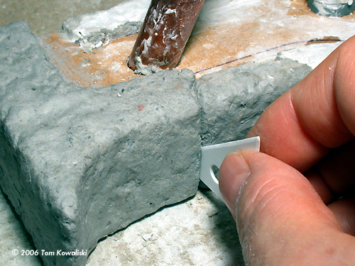
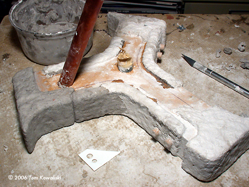
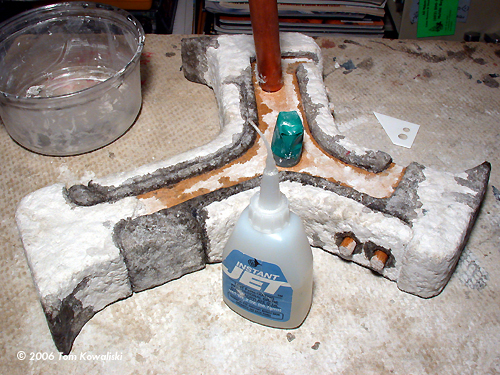
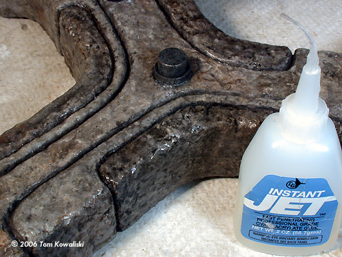
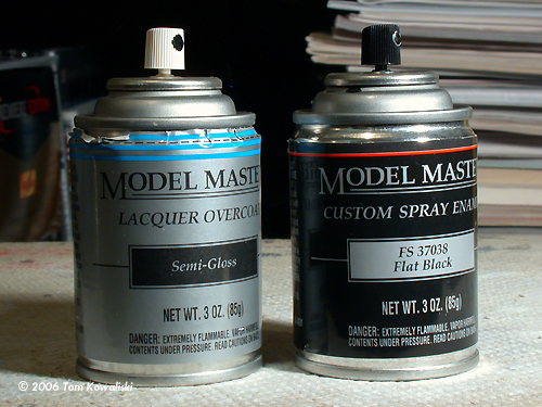
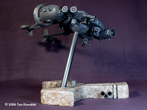
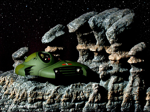
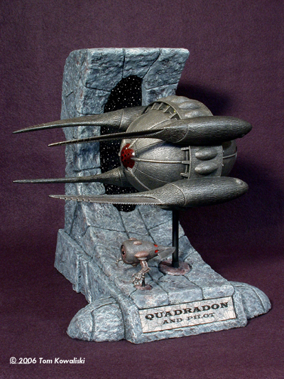
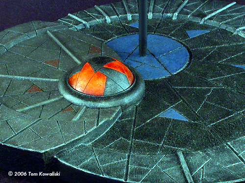
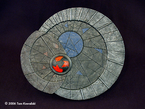
So with the guide, the angled riser hole was drilled and the pipe was temporarily inserted. Now the base's design was traced in a position around the pipe where the ship would be fairly centered above the pattern. It was now almost ready to cut out. But I knew more adjustment would be needed later with the angled riser's height to get the model exactly balanced above the base. Before cutting out the pattern, the battery placement needed to be determined. They would just be sort of lined up and stuffed inside the three spokes somehow. After some measuring I drew the inner lines where the cavity would be cut out for the four C-Cells. That was cut out first and then the outside base pattern was cut out around that. After some sanding, the base was then flipped over to trace its pattern on a Ľ” piece of pressboard that would serve as the top of the base. Using the adjustable angle guide again, another riser hole was cut (duplicated) in the pressboard. A pipe was then pushed through the top pressboard and the base to make sure everything lined up. The two surfaces were pressed together again and then the base was traced on to the pressboard. After cutting it out, it was then glued and clamped to the base to dry for a day (with the pipe temporarily inserted). The new top cover was then feather sanded to the defining edges of the base. The three spoked plug was basically done and ready for wiring and stone work. Before doing any wiring though, the hot rodder in me took over and I stated thinking about where to mount some exhaust pipes on the base. (Don't try to figure it out, I just wanted em) I decided that dual pipes would exhaust right out of the sides of all three spokes. So I drilled some holes there for six wooden dowels that would hold the pipes later. I also got the urge to draw a design of how the Insta-Rock would be segmented on the base. It would be the guide for the stone mason's job later. Well, as it turned out, drawing the stonework design on the base was both a good idea and bad idea too, which I'll explain in the part three. Part Two: Wire The angled riser was still a problem. As stated earlier in part one, the riser's length had to be fiddled with a bit more to get the mass of the ship centered safely above the base. And it had to look “Right” in that position too, where ever it ended up. This was easy enough done by temporarily mounting the ship on the copper pipe and just moving the pipe up and down through the hole until the ship was in the right position, and then just marking the pipe and cutting it. So with that finally done, the riser was cut to length and sanded smooth. Now it could be transformed into an electrical conduit that would contain the male stereo jack and the wiring to run down into the base. As a safety precaution, I also added a little plastic insulator sleeve in the pipe's bottom side wall to allow the wires to pass through unscathed. The typical Ľ” stereo jack available at any Radio Shack is a great little device to use for mounting a ship, with the intent of lighting said ship. They are very strong and allow the model to rotate quite freely while delivering the juice to the LEDs. Even the smaller 1/8” mini jacks are stout enough to support a descent sized model. But the Black Wind is quite heavy. It's filled with lots of lead in its rear end as counter weight. So because of the dimension and mass of the ship, I chose the stronger Ľ” jack which could more easily support its display angle on the base. When I had previously installed the jack's plastic insulator in the ˝” copper pipe, I noticed that it did fit a little sloppily. But a little masking tape rapped around the insulator eliminated all that slop and allowed a very snug and strong fit. A little super glue trickled down the riser barrel locked it in place nicely. I then fed the wires into the pipe and screwed the Ľ” jack into the threaded insulator. Three wires soldered to the stereo jack delivered the juice of two circuits from two battery packs to the ship. I wanted a simple circuit for the base this time but I still wanted two isolated circuits feeding the fifty-plus LEDs in the ship. Sometimes the “bouncing” load of one batch of blinking LEDs (or even one blinking bulb) can cause a spasm in the brightness of other non-blinkers. Isolated circuits would help alleviate that problem. And both circuits could still be turned on and off with one single pole switch breaking the common negative wire going to both 3 Volt battery packs. (See the simple wiring diagram) In truth though, the larger the power source you use to feed an LED circuit, the less chance there is of any bulb affecting the performance of another. All the LEDs are just fed better. So an alternative to my dual circuitry would be to just connect all four batteries in a series/parallel hook-up (as one pack) to still give 3 volts, but at double the wattage capacity. All it would take is just a jumper wire across both positive battery leads to make it all one big battery pack feeding one big circuit. I've already tried that and it worked well, so I may reconnect them that way at a later date. (See “Optional Jumper” diagram) Before mounting the battery holders in the cavity, I went ahead and shoved the assembled copper riser in the base and super glued it in place. I also decided it would be a good time to mount the little single pole switch in its hole. I had already done a lot of pre-measuring even before starting this project so I knew all the components would fit, but it would be a tight fit. So the switch went in and the lock nut went on underneath, and tightened with needle nose pliers. That allowed just enough room for the battery holders to butt up to the switch. I used the smallest screws I had to mount the holders in the base cavity. They still managed to poke through the top plate a little so I cut them off with my Dremel. There was just enough room alongside the battery holders for wire connections to be made and tucked in. And the wooden (exhaust pipe) dowels that I added earlier were also conveniently located for running wires under them. I knew there was one more thing I needed to do; protect the push button switch during all the “masonry” work ahead. It would need a protective sleeve permanently mounted around it to keep the soggy Insta-Rock from gunking it up. I found a round piece of plastic that was just the right size to fit around the switch and high enough to keep the gunk out of its mechanism. Before gluing it on, I went ahead and painted the switch button a couple different shades of stone gray because it would be too hard to paint later. It then got a protective coat of clear Semi-Gloss to give it a hard shell. Then the sleeve was glued on over it and taped up to protect everything. Part Three: Rock This part of the article might be a little disappointing to some folks. Unfortunately the stuff I used for this project apparently isn't available anymore. I bought all my “Insta-Rock” years ago from a local hobby shop. My stash is now all but gone. No one has any recollection of ever handling it nor does the company, “Sierra Pacific Railroad Products,” seem to exist now. I wish I knew the consist of the material so I could try to make it myself. It's totally different than plaster or Magi-Sculpt, or anything else I've used. It seems like it has the properties of masonry cement with a bunch of tiny shredded pieces of fibrous paper mixed in. You'd think there'd be other materials on the market to substitute for Insta-Rock. You may want to do your own search. Or you may opt for using rubber rock molds and Hydrocal, or paper towels soaked in plaster. My other favorite method of creating stonework is with ceiling tile. (Which I hope to do an article on at a later date) It's great stuff. The rock strata for Yoda's S-Wing base were created using ceiling tile. There's many ways to build a base similar to this one, though they might involve some different building methods. Insta-Rock goes on with your fingers. For mountains and natural shapes you can have a real feeling of control with it, or you can cast all thought to the wind and just throw it on and it still looks like stone. You grab a small handful at a time (depending on the detail you're creating), wet it in a bowl of water and just start shaping the rock. For geological formations I like to shape it into eroded strata and outcroppings. For alien landscapes you can just get flat out scary with it, make it look alive. You should think like a stone when doing natural rock formations. Have a basic vision of the shapes you want and then go after it with an un-inhibited subconscious randomness. Now for masonry and cut stone, it's a different process. For the chiseled stonework on this base, it took a more regimented approach. You don't have quite as much freedom because you're adhering to a pattern of predetermined lines and shapes. Designs can be as wild as you want them to be but you have to adopt more of a tradesman like philosophy when laying it on. It's kinda like construction work in the real world. Well, I had to start somewhere so I started laying some Insta-Rock on the base's inside corners first. This gave me a sense of scale and thickness that I tried to duplicate on the rest of the surface. Adhering to the pre drawn lines on the base was a bit of a job but it did give an intentional look to the varying stone shapes with nice rounded edges along the joints. I used a small piece of plastic as a knife edge to help follow the pre drawn sectional lines around the base. This did end up being a bit tedious after a while though. Being hunched over for so long is a little back breaking for someone with back problems. If I was to do it again, I'd probably just cover the whole base with Insta-Rock, or whatever I'm using, and then scribe the dividing lines in later. The Quadradon's Monolith base was done that way. It all hardened way before I even tried to scribe it into blocks. That base was done much more leisurely. Both methods have their pros and cons. Like I mentioned earlier, ceiling tile is another great alternative to Insta-Rock. There's no drying time to concern yourself with. You build your edifice and scribe it when you want. I use a serrated kitchen knife to cut it, or just break it into shape with my hands. Then I use a flat tipped screwdriver blade or a knife to create the joints for block work, and for cracks and crevasses in natural stone formations. Though it is messy, it cuts and scribes very easily. Anyway, I choose the Insta-Rock method and stuck to it. As I'd finish one section, I'd usually let it dry for a day and recoup for the next bout. Before starting the next section, I'd drip a little super glue along the edge of the dried Insta-Rock to seal it. This prevented the next wet batch from soaking it all over again. It also helped cinch it down to the wood a little more securely. I just repeated the same method of globbing it on wet, and then spreading and shaping over and over again until the whole base was covered in stone. Part Four: Color From the beginning of the project I'd been laboring over what colors I'd use for the individual rock segments. And I still hadn't decided on a color scheme, even as the stone work was sitting there drying. Should I try to match the gray color scheme of the ship? What sections would be lighted or darker? I sort of stumbled on to a solution to the color problem that would kill two birds with one “stone.” The base was finally dry now but it needed a little more super glue dripped on it to seal the rest of the stone edges, and to completely cinch the whole thing down to the base. Insta-rock is kind of fragile in a way. It damages easily when bumped or even when just handled sometimes. I noticed that the sections that I'd already doused with CA were now quite hard and very strong. So I took a bottle of superglue and soaked the whole base with it. Well, two things happened. First, it became rock hard like I expected it to. And second, it also turned to stone visually. I mean the colors were dead on. I couldn't have painted it any better than it turned out just stained with the CA. |
|
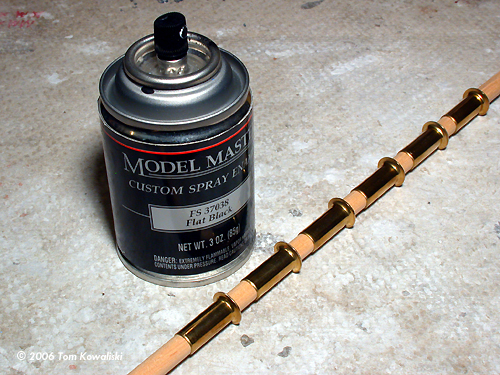
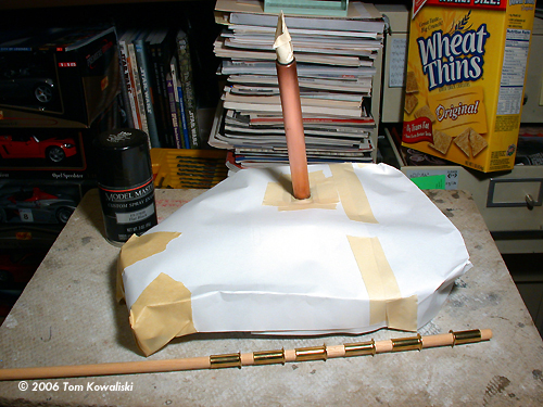
The only colors I added were a slight black wash for the inside corners to give it just a bit of contrast between the blocks, and a tiny bit of brown here and there for some subtle rock colorations. Games Workshop acrylics were used for the thin water washes. But aside from the minor wash treatments, this thing almost painted itself just using the CA glue. I decided that the base looked good with the glossy superglue finish so I went ahead and gave the thing a little more CA where the colored washes had dulled some of the surface areas. I just though the base looked better as a “polished stone” sort of display, and it looked good sitting on the cherry wood desk that way too. And it also seemed to enhance the flat weathered look of the ship. Now all that was left to do was paint the copper riser and the exhaust pipes. The riser got a coat of Testors Flat Black out of a spray can, then a semi-gloss clearcote after that. The six exhaust tips were also sprayed flat black and then dry brushed with Testors Steel. Then they got a coat of clear flat to protect them. I glued the pipes on the base and was just about done. The last bit of painting was on the bottom of the base. It received a brush coat of Testors Russian Earth Gray which seemed to blend in with the rocks pretty well. For the base's foot pads I tried something a little different than the typical felt pads I'd always used. I had some tiny black plastic doll eyes, the type with mounting pins molded in. I drilled two holes in the bottom of each of the stone spokes and stuck them in. The three spoked base now sat nice and level on the desk with just a sixteenth of an inch clearance. Good enough. Conclusion The Black Wind was seven years in the making and I'll never forget the day it was finally finished. Getting its display base also done was icing on the cake for me. I hope everyone enjoyed the build and that it sparked some interest in building your own base, or trying your hand at stonework. I've also included some photos of other bases I've built in the past so you can get an idea of other types of building materials. |
![]()
This page copyright © 2006 Starship Modeler™. First posted on 17 May 2006.
![[Getting started]](bw_base/01Laminating.JPG)
![[Please click to enlarge]](bw_base/32AnotherViewShowingRiserAngle.jpg)
![[Please click to enlarge]](bw_base/39HoldersAttachedandWiredtoSwitchandRiser.jpg)
![[Please click to enlarge]](bw_base/65AnotherLook.jpg)
![[Please click to enlarge]](bw_base/73CeilingTileUsedforRockStrata.jpg)