
|
By Roger Sorensen - images & text © 2006
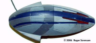
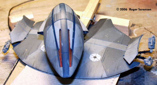
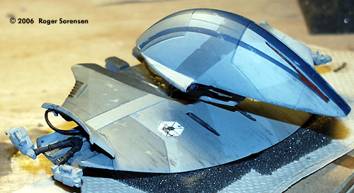
Estes released several model rocket adaptations of spaceships from Star Wars Episode 1. Among them was a Droid Starfighter in attack mode. I picked them up on clearance at a KayBee toy store and put them on my "someday" pile, intending to rework them into models from the movie. This is a rebuild of the fighter into the vulture droid of Episode 3. I began by assembling references. The main reference is the Incredible Cross Sections book from Episode 1. Frame-grabs from Episode 1 and Episode 3 provided additional reference material. Image: Side view, completed modelImage: Front view Image: Steely-eyed gaze |
![[Complete]](rs_droid/01_asm_onbase.jpg) |
|
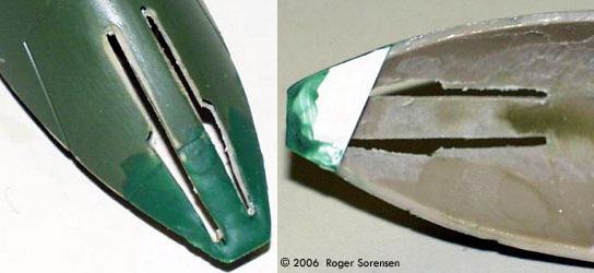
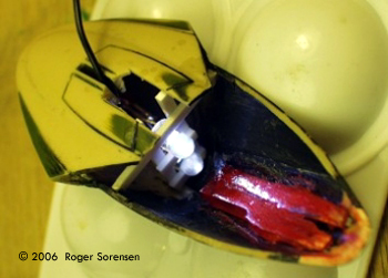
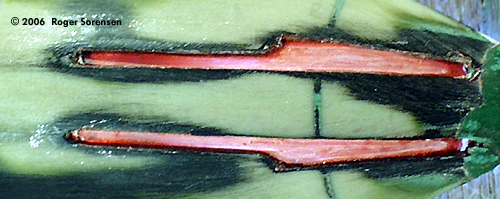
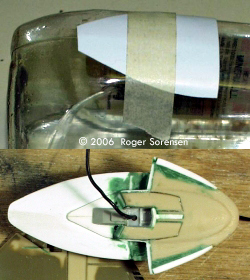
Image: Deconstruction Image: First, the nose was re-shaped Image: 'Eyes' were cast in clear resin Image: LED installed Image: Interior of the head
Image: Closer look Image: Building up the backside of the head
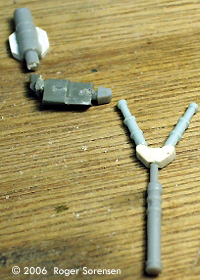
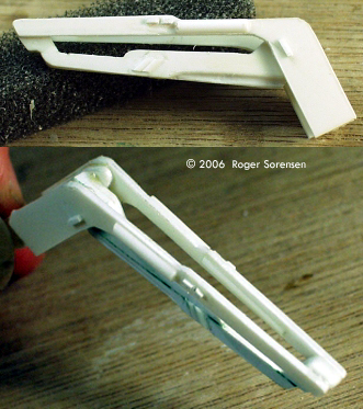
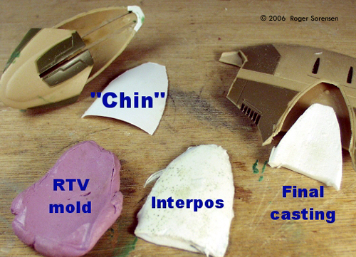
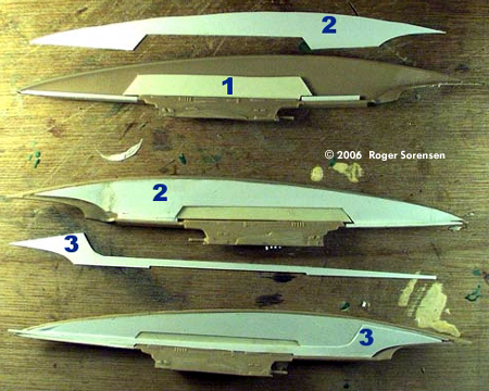
Image: More views of the neck Image: Making of the 'shoulder' Image: Bay covers
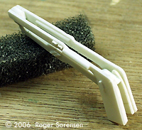
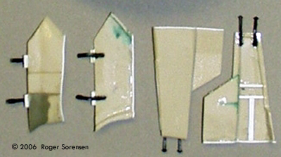
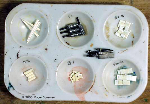
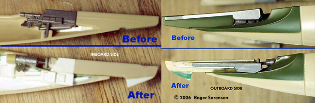
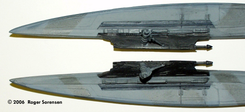
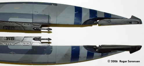
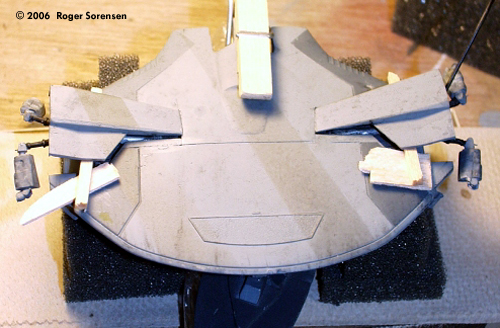
Image: Duplicating the parts Image: four-plicate claw parts Image: Before & after detailing the claws Image: Building up the legs, by the numbers Image: Detail view - triangular ring at the tip Image: Inboard detail Image: Inside face, before & after Image: Outboard side details Image: Painted head Image: Legs Image: Body Image: Bottom/inboard sides Image: Head, weathered Image: Body, weathered Image: Upper legs Image: Lower legs Image: Setting the angle of the bays Image: Head and body Image: From behind Image: A quick and dirty jig helps attach the legs Image: Attachuing the legs Image: Last but not least, the power pack |
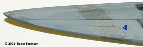
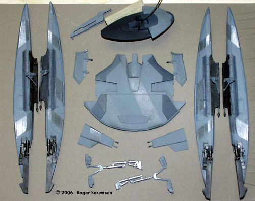
Getting Started To begin the conversion I had to dismember the Droid fighter. Using a razor saw (both large and X-acto tool size), I cut away the four wing / leg pieces and the “head,” then trimmed away the four body panels which, when closed, cover the leg struts. I used Dremel tools, files, and sandpaper to clean excess material away from the inside surfaces of the four panels and to open the “eyes.” Head & Shoulders I had to reshape the nose on the droid head, since it was more rounded than it should be. Sheet styrene and thinned green putty accomplished that. After the putty dried, I sanded it down to shape. I painted the interior of the head black to reduce light bleed-through from the LEDs that would be installed. The eyes are clear resin castings. I pressed fast-set RTV putty into the inside of the head to obtain an RTV positive. I coated this with liquid latex for a negative mold which I filled with clear polyester resin to obtain the final eyepiece. This piece was trimmed and pressed in place to fill the eye openings in the head. I painted the eye piece with a mix of Tamiya transparent red with a bit of Acryl pearl white. I then scored the casting slightly to let more light through for the brighter forward area. Two white LEDS (wired in parallel, with a 100-Ohm resistor in series) inside the head illuminate the eyes and are powered by 3 lithium coin batteries in series (9 volts). The 'white' LEDs have a distinct blue tint, so I painted them with a light coat of transparent yellow to rebalance the color. The wire leading out of the head will go to the batteries. I put together a small armature out of strip styrene to fit inside the head and hold the LEDs in position. I covered the bottom of the head with sheet styrene formed to a compound curve, made by stretching heated sheet over a suitably-shaped bottle. I added sheet pieces and parts box pieces to detail out the area where the neck struts attach. I used strip styrene to build out the side-aft flanges so they have the correct rounded contour, drilled out the inside of the flange and install small bits of 1/16” aluminum tubing for the detail piece. Does it all work? Yes!! Sigh of relief and... on to the neck and body. Neck & Body I made the neck strut from 0.06” and 0.1”sheet styrene cut to shape and detailed with other styrene stock. More sheet stock went into linkages to connect the neck to the head and the body. The body piece needed to have pieces added in the area where the head would retract when in flight mode, and in the interior of the leg strut bays. For the head area, I made an RTV mold off the bottom of the head, a resin interpositive, and finally a resin negative piece which matched the contour of the bottom of the head. I trimmed it to fit and glued it in place. I bored out recesses in the piece to (theoretically) accommodate the neck when the droid head is retracted. Naturally, after the fact is when I find the schematic for what the body aft contour looks like when the head is extended. I lined and detailed the insides of the leg strut bays and covers using sheet and strip stock. More bits from the spares box serve as hinges. Legs The struts and linkages that connect the leg to the body are scavenged from spare landing gear and various other cylindrical parts, detailed with additional styrene stock. Once I had parts for one strut, I made an RTV mold and cast the struts used on the model out of urethane resin. The casting for the body strut was reinforced with wire. The legs from the starfighter were lacking in detail and were too thin. I removed the walking claws so they could be detailed and placed in proper walk-mode position. The existing claw actuator detail was way underscale, so I replaced them with parts made from sheet & rod styrene, small springs, metal wire, and parts box pieces. I built out the inboard surface and edges of the legs with sheet styrene to the proper thickness and re-detailed to match the detail shown in the cross-sections book. First, I cut and installed the three layers that would build up the inboard surface:
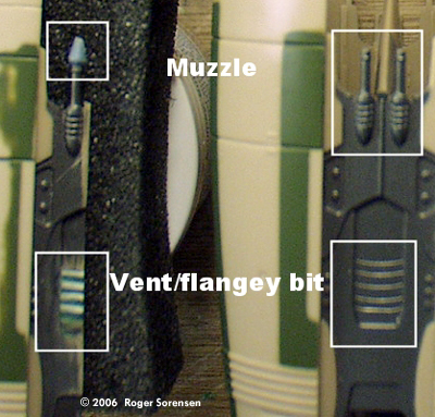
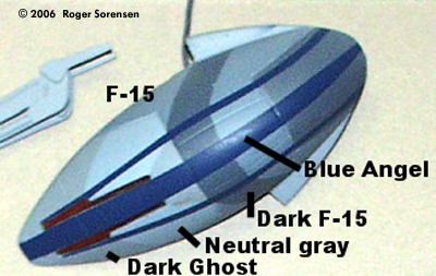
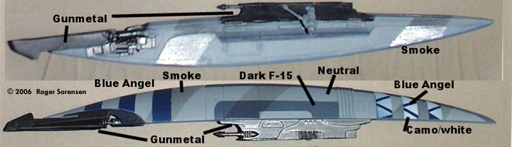
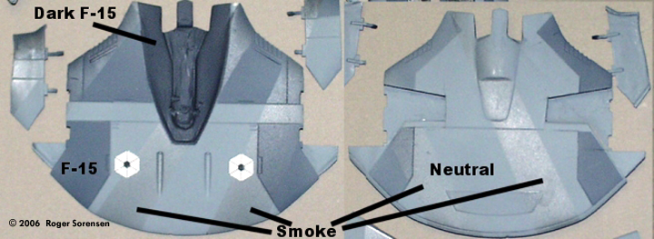
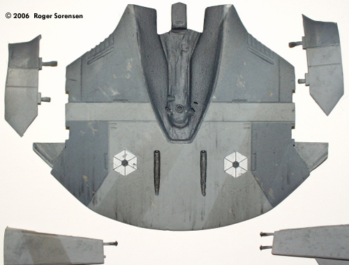
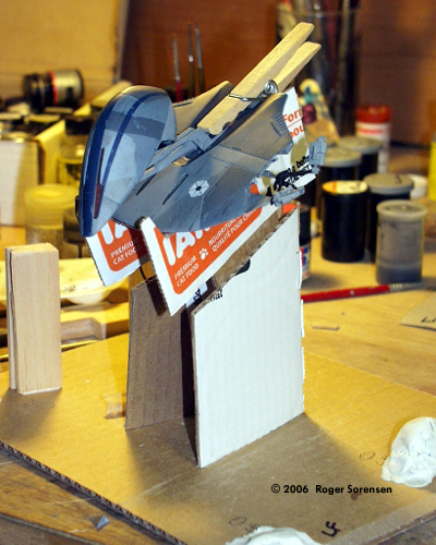
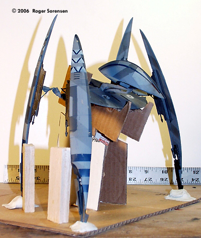
After the sheet panels were installed, I scribed panel lines into them. The area in the center of the leg was missing a hefty detail piece. I built these up in 4-plicate by building onto four pieces of .06x.1" strip with details of smaller strip added. I cut the assembly apart and trimmed each piece. The pieces went in place as shown in the photos. With the addition of a larger gun muzzle and added detailing using small strip and half-round styrene, the inboard legwork was mostly done. On the outboard surface, I used strip styrene & putty to build out the set of small flanges which had been done simply as engraved lines by Estes. I made the cone-shaped laser muzzles out of styrene rod turned using my Dremel as a mini-lathe and an X-acto knife as a shaping tool. (Same trick I used in making detail bits on my Vulcan Shuttle 'Surak') Painting & Detailing The first round of painting on the parts was for overall color of the body, head, and legs - Model Master (MM) neutral gray. I masked off the appropriate areas with blue painter's tape prior to airbrushing the darker panels with MM F-15 gray, a darker F-15 gray & black (3:1) mix, and dark ghost gray. I temporarily attached the strut bay covers so they could be masked & painted at the same time as the body. The walking claws and laser cannon areas are Metallizer gunmetal. The leg struts are Metallizer stainless steel and neutral gray. The "V" section of the struts would later be painted black. The larger body-end piece (spare Nostromo leg parts) would be removed, since it wasn't necessary for placement of the struts. Detail colors and triangular insignia were painted Blue Angel blue, and a camo gray/white (1:1) mix. The “shadow bars” are Tamiya transparent acrylic smoke. The body's hexagon markings are ALPS-printed decals (black on white decal stock). Weathering Now the fun begins - dirtying up a nice, clean paint job. The weathering was done using a variety of techniques – X-acto scraping, sandpaper scuffing, pastel dusting and streaking, and black acrylic stipples / washes. After I finished all weathering, I gave the non-metallized ares of the parts a couple coats of Testors Dullcoat. Final Assembly With all parts finished, the only remaining task was to put it all together. I began with the head-body assembly. I first attached the neck to the head, running the eye-light wire along the inside of the neck. I had drilled small holes into the resin piece in the body. The wire runs from the neck into the right side of the body and out through the right-side strut bay. After threading the wire, I attached the neck to the body. Next I attached the leg struts, then positioned and attached the strut bay doors. I used small shims of balsa to prop the bay doors in position while the cement set. With a little more time and engineering this would have gone easier. The plan was to place the body assembly on a cardboard jig to hold the body in its proper walking posture, superglue the leg assemblies to the struts, and then transfer the model to a display once the superglue had set and the model was stable. Stable. Yeah. Right. First off, I had forgotten to rotate the leg struts when I installed them, to account for the 15-20° tilt of the body in walk position. And of course, superglue always takes longer to set than you want to give it. And all this was happening under a deadline for submission to an online model contest. It looked good on paper - or rather, on cardboard and sculpey. But the strut joints just didn't want to hold for the transfer to display base. I should have had more of a socket-fit for those parts. So, the end result (with about eight hours to go before the midnight deadline) was that I assembled the thing onto the display base. And, because of the non-rotation of the struts, the left rear leg just wanted to be about 3/4" up off the base, so it's mounted on a small acrylic block step-up. In the End.... So, finally it's together. And not going anywhere, being glued to the base. The base is an 8x10-inch sheet of foamcore topped with a sheet of acrylic glazing. The center support - necessary 'cuzza that darned gravity thing - is also acrylic glazing cut to strips. Eventually, I'll detail & paint the base so it looks like a bit of starship surface. But, for now, there it stands. The final thing was to add the battery pack - three 3V lithium 'coin' batteries fitted into a clip made of heat-softened sheet styrene which I wrapped around the battery stack. I ran the ends of the wire through the sides of the clip. |
![]()
This page copyright © 2006 Starship Modeler™. First posted on 17 April 2006.
![[Starting Point]](rs_droid/02_droidfighter.jpg)
![[Please click to enlarge]](rs_droid/03_VDroid_parts.jpg)
![[That worked]](rs_droid/09_eyetest.jpg)
![[Please click to enlarge]](rs_droid/19_leg_panels.jpg)
![[Please click to enlarge]](rs_droid/25_DroidKit.jpg)
![[Please click to enlarge]](rs_droid/26_paintage.jpg)
![[Please click to enlarge]](rs_droid/30_Parts-topside.jpg)
![[Please click to enlarge]](rs_droid/38_asm_head_body2.jpg)