
|
By Nick Sadler - images and text © 1997 This article originally appeared on Quantum Science Fiction Magazine, and is reprinted with their kind permission. Chances are that if you're reading this page, you've just got your shiny new Robot kit. First of all, CALM DOWN. If you want to get the full potential from this very detailed kit, there's a lot of work ahead. If, like myself, you've only modelled starships before, the Robot kit will bring a fresh challenge and new experiences to your kit building repertoire. Normal practice with starship kits is that the painting takes a great deal of time. Here, in most cases, the painting parallels the building. We've all become obsessed with trying to get our tiny kits up to studio model quality, and there are very few pictures of either the Lost in Space Robot, or the Jupiter 2 studio models. I have managed to find a few pictures of the Jupiter 2, and of the full size Robot at a Lost in Space convention. In this article I will make references to the original ERTL/AMT plan for building, as well as my own photographs in an effort to make things less confusing. As always, the first thing to do is to familiarise yourself with the parts while they're still on the trees. The next step is usually to remove the flashing from around the pieces. As there are a good number of pieces in this kit, it is very tempting to remove the smaller pieces to clean them. Don't! This is how they get lost. Instead, clean the pieces as you remove them, keeping all of the trees - they'll come in handy for a spot of scratch-building later. Early preparations could include giving the large armour plates a few coats of paint. STEP 1: First, remove parts 40 through 43 and paint them unassembled. I used matt paint partly because semi-gloss is unavailable in my area, but mostly because it sets off the gloss of the clear parts better. (I used Oxford blue Humbrol enamel matt thinned to the consistency of milk. With correct drying times, this does take a ridiculous amount of time. I found that leaving the painted part under a warm lamp doesn't hurt.)
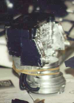
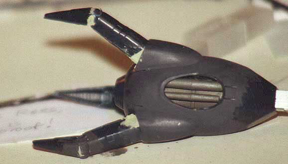
STEP 2a: First, decide whether you want the Robot tall or short. I chose to build it tall. Assemble parts 37 together and clean up any open seams with a little putty. Sand with about 800-grit glass paper or silicon carbide paper. Making sure the assembly is dust free, paint it chrome silver. Now glue part 35 to part 36 as shown in the plan. A little seam repair is required around these new assemblies. The rounded end (not the end with the detailed centres) doesn't need much attention as it is hidden later, so just paint them silver. STEP 2b:
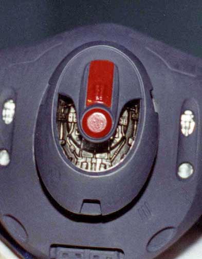
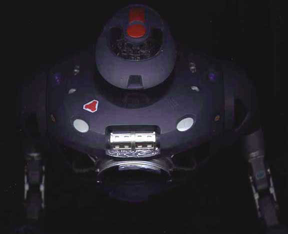
Part 39 can be added now or later. I painted it black then dry-brushed it with some chrome silver - this picks out the moulding on the surface of the part and makes it look more metallic. (A1) [N.B If you add this piece after the two halves have been joined, glue it onto the supports on each side.] STEP 3: Paint part 47 as shown on the plans and paint the other two parts involved in this step. If I remember the film, the lower rectangle of part 47 is a display panel Go mad! Next glue this in place on the inside of part 9. (When gluing a painted surface against a painted surface, I use Instant bond cement. Yes it does dissolve the paint as any other type, but it sets much faster). On parts 8 & 9, painting isn't necessary yet on the sides but do paint the top and bottom. Assemble parts 8 and 9 (with part 47) around the short stems of assembly 2B. Putty and sanding is only necessary at the very front and the back for now, however, don't paint over these worked areas yet. STEPS 4a & 4b:
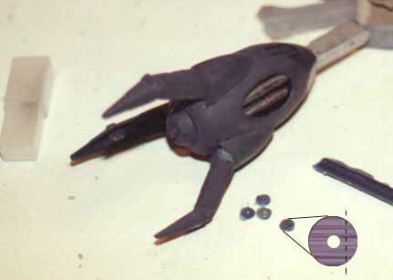
For each 'arm', build from the 'hand' to the 'shoulder'.
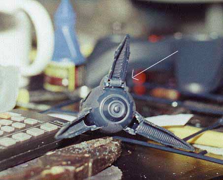
The process is much the same for 'STEP B' take care not to fix part 29 into part 50 too well, as the spinning joint won't spin. STEP 5: In this step, that warm lamp takes on a different role. You'll probably find that the two arm assemblies are warped and don't fit against the sides of the lower torso properly. You could use the lamp to ease the plasticity of the part then glue it into place. If this method doesn't appeal to you, just glue the two parts and clamp all the edges to the torso with a length of tape.
The clear piece in this step of the plan can be added now or later. If you choose to add it now, then I suggest using instant bond cement and glue around the edges, not underneath (a mistake I managed to make!). This way, any slip-ups you may make are easily solved and easily hidden! With each edge of this piece glued, it is very tricky to manoeuvre into the space without getting gluey fingerprints on the shiny surface. Tip: cover the flat end of a pencil with masking tape, with the sticky side out, then stick the front of the panel to the pencil. Perform the cementing while the part is attached to the pencil, and glue in place.
STEP 6:
STEP 7:
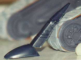
The first task is to take however many fingers you want to alter (part #21). First, look underneath at the 'cowl' portion, there are 3 small tabs which fit into holes in part 20 (try a dry fit it doesn't). Cut off the tab which correspond to the cut at the edge of part 20. The cowl will simply be anchored in the other two holes. Now cut the finger from the cowl portion at the angle given by the moulding. Glue the finger back on but at a higher angle this is made easier by performing the following two tasks:
2. Join them together at your chosen angle, then prop it up, and allow to set for about an hour, or even overnight. Attach them to part 20. Now use putty to fill the gaps that have been produced. Remember the trees you kept? They come into their own here. Find the part of the tree with the widest diameter and cut three lengths to the same width as the hole beneath the finger.
4. If you wish to bend the finger at the second knuckle also, as I did, read on.
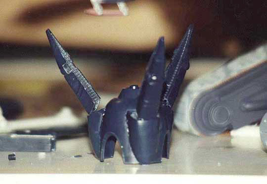
- In keeping with the base knuckle, make a hinge here by cutting lengths of slightly narrower tree and gluing them in where the knuckle bends. - As on the 8ft 'studio model' the knuckle joints are light and metallic, so paint the knuckle and hinge bars silver. This provides a better contrast and suggests that there is more than one part to each finger, when painted in this manner. It gives the impression that the knuckles and hinges are all separate pieces.
- There is quite a lot of flash on the underside of the fingers, small semi-circular protrusions these need to be cut or sanded away.
PLANS Right, back to business: when building the hands closed, I found it easier to attach the fingers to part #20 and clean up any open seams with some putty. Sand the unit and paint as a whole, the central silver area doesn't present too many problems when painting through fingers. Paint part 49 flat black, and fix part 12 to 13. The plans suggest painting these separate colours, but I haven't found any instance in which this colour difference is visible, so I cemented the parts and sanded the seams away, then painted the unit chrome silver. Do the same for the part assembly 16 & 17. Paint #18 the plans tell you aluminium, however aluminium stands out too much, even though the part is well covered. I used Gunmetal; it's dark but slightly metallic so it stands out enough. Paint part 19, then take the 16/17 assembly and glue it through part 19, to #18. Leave this to dry thoroughly as the fit is quite loose. Now glue this assembly to the upper-hand/finger unit. The seams here are very large so make up the difference in height with putty then use a slightly harsher glass paper to flatten the gradient finish sand with the 1000grit and paint as normal. Masking maybe necessary where the hand meets the silver arm. Next, when connecting the two halves of the arm together using parts 14 & 15, make sure the parts are fastened very securely. N.B: The arms are supposed to be fully poseable, but if these joints are weak, the hinges won't support the weight of the arm. The result is a robot with limp wrists. For my model I picked some dynamic poses and fixed the joints the two that I left unfixed were the joint for sideways movement at the shoulder, and the large circular joint itself. STEP 8: This is a strange step. With this method, it's very easy to push the cowl (part #11) too far onto part #10; this almost eliminates any chance of the joint spinning in the socket. I performed a dry fit of the two armour halves with the disc joint in place. This step works better if it is performed at the same time as step 9. - Take assembly #6 and fix it firstly to the front half of the armour (tricky). - Paint parts #10 then put in place and cement the back armour around them to the front piece. - When the assembly dries, fix the seams across the top of the shoulders then paint. - Paint parts #11 then cement in place be careful not to glue them to the armour. - Now attach the arm assemblies to the shoulder joints. STEP 9:
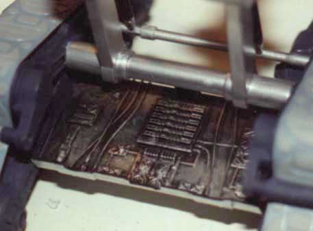
STEP 10: When attaching the torso to the lower midriff I found it easier to remove the front tab from the cylindrical area of the torso. This part is supposed to fit through the circular cut-out in the midriff. Without it there the fit is just as good, but you don't risk snapping the edge of the hole. Decals: everyone has they're own technique for applying decals my advice is to stick with what works for you. I heard of a substance that removes the gloss from them, but I can't find it this would be ideal for this kit, especially if you have used matt paint. Of course, if you're using varnish, then good for you, but if you know where to get this substance then let me know, because I've been searching for years.
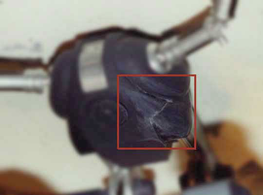
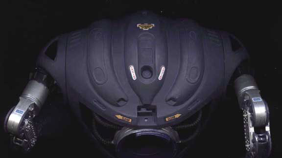
Last Word: There seems to be a curious hole at the bottom of the back armour plate I can't find a function so I filled it and sanded it. In Conclusion. These steps aren't the definitive, or correct ways to perform the assembly of this kit. They are merely suggestions from an enthusiast. I hope that over these pages I have provided possible methods or inspiration for improvements so that you can find aesthetic looks and effects. If you have any questions, improvements, or if you want pictures then email me at nicksad@cableinet.co.uk. Thanks for reading. |
![]()
This page copyright © 2000 Starship Modeler™. Last updated on 30 November 2000.
 Next take the pieces of track and paint the top side base colour first. When this is dry, paint the reverse side the plans suggest brown, but I found that orange suits the part better. After this side has dried completely (maybe even overnight), return to the tracks and paint the raised patterns on the top side. After this, carefully paint the sides the same orange colour revealing the tooth shapes (as shown on the box art).
 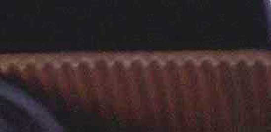 Now glue the track together without the motor structure so that there are 2 loops of track, one for each side. When the glue has set thoroughly, assemble parts 40 and 42 by bringing them together from either side of the assembled track. Paint and add the roller. Repeat the process for the assembly of parts 41 and 43
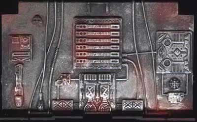


 During drying, the parts
may spring away from the torso. If this does happen, add putty to these
holes and sand them. Sanding will also be necessary on the top of this entire
assembly where the curves meet the straight sides. Once dust-free, the puttied
areas can now be painted.
During drying, the parts
may spring away from the torso. If this does happen, add putty to these
holes and sand them. Sanding will also be necessary on the top of this entire
assembly where the curves meet the straight sides. Once dust-free, the puttied
areas can now be painted.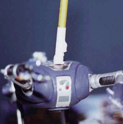

