
|
By Phil Gruver & Dave Rosignoli - images & text © 2003
November 1975: I remember waiting in eager anticipation for my 12th birthday to arrive so I could build up that Aurora Spindrift model that had been sitting in my parent's closet since the summer. It had been reissued sometime before and I begged my parents to buy it. I so much enjoyed Irwin Allen's Land of the Giants TV show and even made several cardboard model versions of it. |
![[Click to enlarge]](pg_logs_Fig00.jpg) |
|
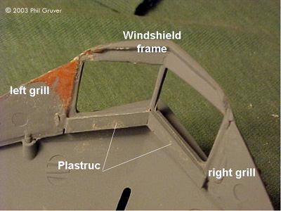
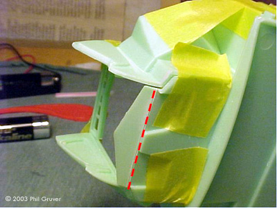
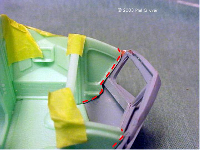
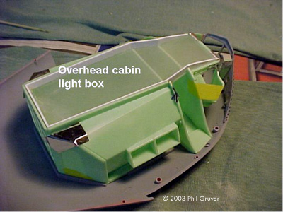
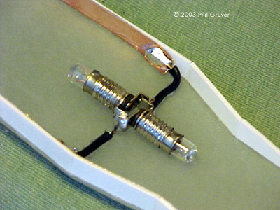
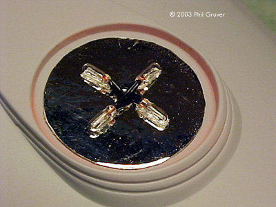
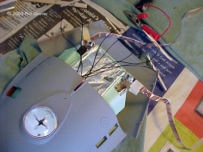
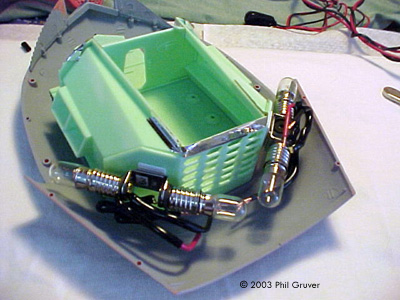
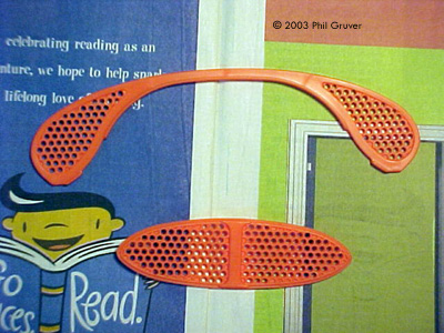
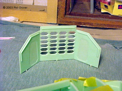
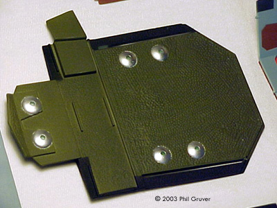
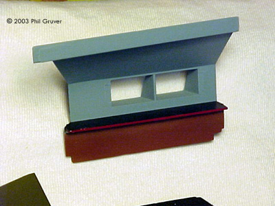
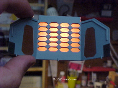
Image: While the glue bonding the grills to the lower hull dried, Phil taped the upper edges of the grills to the forward shroud to ensure proper alignment. Image: The end result was a nearly seamless fit to the removable forward shroud. Image: Internal parts were temporarily taped together during the trim and fit-checking phase of the spacecraft buildup. Image: The cockpit internal surfaces needed to be trimmed so that the forward shroud and lower hull would fit together properly. Image: Some trimming of the walkway and sidewalls were also necessary. Image: Plastruct and sanded clear acrylic were used to construct overhead cabin light box. Image: Two 3V bulbs were soldered together in parallel and soldered to two strips of copper tape. Image: Four rice grain 1.5V bulbs for the dome were wired in series-parallel to the same 3V bus used for the cabin lights. Image: The top of the light box was closed out with aluminum foil and all wires were routed to the aft compartment. Image: 6.3V bulbs for the exhaust/intake and aft bulkhead lighting were bonded to the internal structure. Image: Drilling these surfaces was easier than it looked. Image: Cutting the polygons was more time-consuming. Image: Shapes cut out of clear acrylic were sanded to diffuse the light source and eventually painted with Tamiya Acrylic Red. Image: Key sections of the floor were masked and painted with flat OD green, flat black and silver. Image: Seat details were hand-painted. Image: Cabin sidewalls were masked and painted. Image: The aft bulkhead with clear acrylic window is held up against a lamp in the background. Image: Some surfaces including the oval-shape display were constructed on a PC using PowerPoint. Image: Light trapping was accomplished with flat black paint and aluminum tape. Image: Displays were constructed in power point and adhered with double-sticky back tape. Image: Note the signal pattern on the starboard display. Image: Cutouts in the display base for electronics were closed out with thin plywood from a smoked salmon box. Image: The oscillating light electronics and all batteries and switches were contained within the base. Image: Cross section of display base showing cutout for electronics |
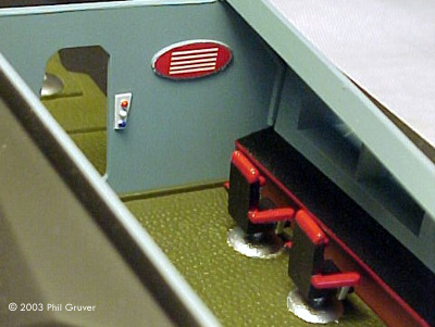
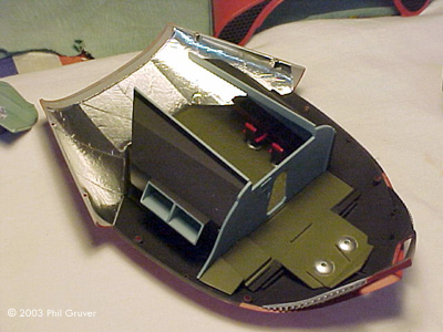
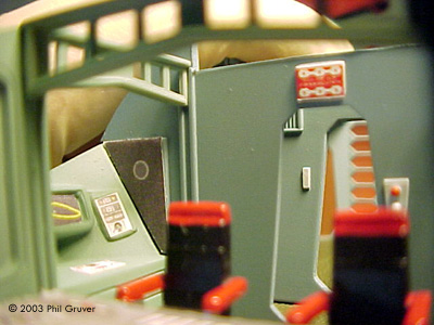
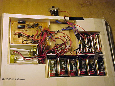
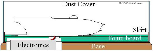
But the wait was over. I opened the kit, built it up and hand painted it. It looked so great, I even built a second one some months later with money from my paper route. Both models saw a fiery end resulting from a cabin fully packed with leftover fireworks later that year. Before the destruction, I did manage to strip the models of their domes, chairs and figures which I kept in a box in my mother's attic. June 2002: The wait was over, again. Polar Lights had issued a version that is nearly identical to the original Aurora model having back-engineered most of the parts. No need to shell out $300 on Ebay, the Polar Lights version was only $19.95 at the local hobby store. With this model I hoped to recapture fond memories of building a campsite in the woods behind our house. This time, though, the campsite would be a diorama and lighted with bulbs instead of gun powder. Building From the Outside In I still recall the frustration of not getting the forward shroud to mate properly with the lower hull especially around the windshield and grills. Although Polar Lights has made some marvelous improvements to the model,, including the four very large pin inserts to hold the forward shroud in place, the problem was and still is the internal structure is too large for the outer shell. I solved this problem by working my way from the outside in. I started by mounting the forward shroud to the lower hull. The four very large and sturdy pin inserts were a great design feature with this update. I then glued the left and right grills to the lower hull and taped the upper edge of the grills to the curved edge of the forward shroud to ensure proper alignment. Once these parts dried, I then inserted the windshield frame in place between the grills. I used Plastruc and Squadron White putty to raise the bottom edge of the windshield frame so that the top of the windshield was flush with the curved edge of the forward shroud.With the outer shell geometry aligned, it was now a matter of trimming to make sure the internal structure did not deform the outer shell once installed. All internal parts were temporarily taped together for this purpose. I started by introducing a break in the forward triangular part of the floor forward of the pilot/copilot seats. Doing so allows the floor to rest inside the guides of the lower hull without deformation. It also provided a foot rest for the flight crew. Next I trimmed as much as 3mm of the forward and bottom edges of the cockpit sidewalls using a hobby knife and file. The plastic in this model is relatively soft and easy to shape and smooth. The outboard edges of the hallway floor and walls were also trimmed so that the floor would sit properly in the lower hull. Light 'er Up! This is a lighted model. I wanted to capture not only the static cabin and dome lights but also the oscillating intake/exhaust and the aft bulkhead lighting. The overhead cabin lighting consisted of a box designed to hold two 3V light bulbs. Channels were cut in the top of the hallway walls. The bottom edge of the channel is at a level flush with the top edge of the cockpit I-beams. The box was constructed from a piece of clear acrylic sanded with 600-grit sandpaper to diffuse the light source. The sides of the box were cut from Plastruc and glued to the acrylic with cynoacrylate. The two bulb sockets were glued together and each bulb was soldered in parallel to a pair of copper tape strips that run the length of the box. The intent of this was to have a common 3V bus to solder into should I decide to add more cockpit lighting at another time. The top of the box was then closed out with aluminum foil adhered to the edges with double-sticky back tape. The dome lights consist of four rice-grain 1.5V bulbs mounted to a disc cut from Plastruct sheet styrene. The top of the disc was covered with a shiny aluminized Mylar tape. The four bulbs were paired in series and the leads soldered in parallel to the 3V leads at the aft end of the cabin light box. Sufficient slack in the bulb wires allowed for easy removal of the forward shroud. The oscillating lights consist of four 6.3V bulbs. The circuit is explained in the sidebar. The four bulb sockets were mounted to the aft bulkhead. The static and oscillating light wiring was bundled into a single harness that was snaked through the mounting hole in the lower hull after final spacecraft assembly. The intake and exhaust ports were drilled using an electric drill and the aft bulkhead polygons were cut with a hobby knife and smoothed with a file. Clear acrylic shapes were cut and sanded with 600-grit sandpaper. These were subsequently airbrushed with Tamiya clear acrylic red. Double-sticky back acrylic tape was used to mount these to the intake, exhaust and aft bulkhead surfaces. Painting the Spindrift & Crew Much of the coloring was based on screen snaps of the TV show I keep in a reference notebook. The exact colors were difficult to determine as they depended on the lighting scheme that seemed to vary between episodes. When in doubt, I chose a color that was aesthetically pleasing. All surfaces were primed with Floquil primer. All parts except the flight crew, passengers and seats were airbrushed. The kit comes stock with a pilot (Steve Burton), co-pilot (Dan Erickson) and stewardess (Betty Hamilton). After rummaging through the attic (thanks, Mom!) I found additional �passengers� from the original 1975 and other kits. I created a Mark Wilson character by taking the co-pilot, rounding the top of the head, straightening the legs and arms, and carving in a blazer over his shirt. I used the Flying Sub Admiral Nelson character to create a seated Fitzhugh. The characters were hand painted with various mixtures of Testors enamels. I used flat light tan for all skin colors (Dan's was darkened slightly). Basically I poured a bunch of different colors around a plastic transparency and then mixed in the middle until I got a match with what I saw in the pictures. This included Steve and Dan's inverted gray and red jum suit colors; Steve's brown hair; Dan's black hair; all black shoes; Mark's dark gray slacks and blazer, white shirt and grayish blond hair; Fitzhugh's military tan shirt and pants, and black hair; Betty's dark tan jacket and boots, yellow shirt and nylons and blond hair. The spacecraft outer shell primary color consisted of about 70% Model Master �Go Mango� and 30% flat red to get just the right sheen. The stripes were made with varied mixtures of Testors black and white gloss paint. The forward grill and antenna were painted with Testors silver. All interior surfaces and intake and exhaust port surfaces were painted with Model Master flat black. The outer surface of the dome was painted with Tamiya clear acrylic red and the interior surface of the dome was sanded with 600-grit sandpaper. The floor was painted with Testors flat OD green darkened with flat black. Outboard edges were painted flat black. The seat mounts were painted silver. The seats were airbrushed gloss black and then hand painted red and silver. The cabin sidewalls were painted light blue (50% gray, 40%blue, 10%green). The shelf was painted gloss black with red trim and the baseboards were painted Burlington Northern Brown. The outboard surface was painted flat black. The aft bulkhead was also painted light blue and brown. The hallway walls that separate the cabin cockpit were also painted light blue and flat black. Details were hand painted. The oval passenger screen was created in PowerPoint and adhered with double-sticky back tape. The aft end of the lower hull was covered with aluminum tape to concentrate the oscillating light source. The interior surface of the aft shroud was similarly covered. The cockpit walls and I-beams were painted a sort of �anodized green� (60% gray, 10%blue, 30%green). Console images were created with PowerPoint and often consisted of images taken from various reference sources found on the Internet. The aft shroud is not glued but instead held in place by the tail. The tail is also not glued in place. This allows for access to the four 6.3V bulbs should replacement be necessary. The rice-grain bulbs and overhead cabin light box are accessed by removing the forward shroud. Building the Ultimate Campsite The display base purchased from a craft store was cut out to house the static and oscillating light electronics. Thin plywood scrap was used to close the bottom of the display. Felt padding was adhered to the bottom of the display with double-sticky back tape. The circuit board on the left contains the electronics for the oscillating lights and is powered by the six 9V batteries on the lower right. Two knobs that control the amplitude and frequency of the oscillation are set and enclosed below the circuit board. The four AA batteries provide the static 3V lighting bus for the cabin and dome lights. A cutout at the top edge of the display base was subsequently added for the two On/Off switches. Because of the thickness of the electronics package and the need for more volume to contain wiring, the campsite was built on top a sandwich of four pieces of 3/16� thick foam board purchased from a craft store. The bottom two layers had cutouts to contain the upper portion of the electronics and the top two layers had a cutout for the wire harness to pass through and also a large rut for the spacecraft to rest in. The upper two layers also facilitated planting various plants and trees without the risk of penetrating the electronics. The four layers were adhered together with double-sticky back tape. 1-1/8� wide strips of thin plywood were used to create a skirt around the perimeter of the foam board sandwich. The strips were bonded to the foam board with double-sticky back tape. The resulting 3/8� lip around the perimeter prevented the joint compound, dirt and other debris from falling over the edge. A dust cover made from 1/8� thick clear acrylic purchased from Acrylonics of San Jose, California encloses the campsite after final assembly. At this point the spacecraft was loosely mounted onto the foam board and carefully wrapped in a light plastic bag to protect it during the assembly of the campsite. The wire harness was then snaked through to the other side and soldered into the electronics package. |
|
Why I'm Glad I Kept that Joint Compound Although Woodland Scenes putty is recommended, a large leftover container of ProForm All-Purpose Joint Compound used to repair a wall in our house years ago was available. I put a ~3/16" layer of this material down on top the foam board, allowing for depressions in some places and rises in others, particularly around the perimeter of the ship or where trees or rocks were to be mounted. The large rock that forms the back wall of the lean-to was taken from my front yard. The tree stump that holds up the other end of the lean-to was taken from a local park. These items and the ubiquitous rock in front of the campfire were mounted directly into the joint compound. I let this sit outside for a day and dry in the sun. I then filled in the ensuing cracks the next day with additional joint compound and proceeded to cover the campsite with very fine dirt adhered with 3M Super77. The dirt - the color of which matches that of the show - was taken from a creek-bed at a local park. Realism was achieved by throwing on varying levels of dirt (this model is by no means gravity-proof). The trees and shrubs were taken from various parts of California including Serra Park, the UC Berkeley Campus and Monterey. I found that in most cases if I applied a thick layer of Plaid's FolkArt Clear Coat Extra Thick Glaze immediately after clipping the plant and hung the plant upside down it would turn solid but keep its natural texture indefinitely. I found the best way to �plant� these was to create a hole by driving a screw driver down through the joint compound and into the foam board, and then inserting the stem of the plant into the hole. The deepness of the hole and the dirt falling in around the stem provided a firm rooting. I then used a brush to pile the dirt around the base of the plant. After a long rain some weeks ago I found fallen bits of stems, leaves and lichen and kept them in a plastic bag until they turned into a brownish/greenish potpourri. This I ground up with my fingers directly over the campsite so as to make a natural looking �carpet�. |
|
|
After some experimentation I found the best material for the lean-to was a discarded rubber surgical glove and one of my wife's nylon stockings (thanks, Pet!). I staked two 1-1/2� long needles on either side of the tree stump to form two adjacent corners of the lean-to. The opposite side of the lean-to was the rock. I then laced white thread through the needle eyes and then around the rock. I cut a jagged square of the rubber glove and put double-sticky back adhesive on one side and stuck it to the thread, creasing the edges. I then cut a jagged square of the stocking, placed double-sticky back adhesive on one side and stuck it down slightly askew on top of the rubber glove to act as camouflage. The cots inside the lean-to were constructed from small branches glued together with Elmer's glue. More stocking material was used to make the mattresses, pillows and blankets. The table and stools were made from stirring sticks and toothpicks. The step ladder leading to the ship was taken from the Hasegawa 1/72 US Pilot accessories kit, trimmed and painted aluminum. The axe was made with a small strip of wood with a strip of aluminum superglued at one end. The end of the axe was colored with blue and red Micron pens to make it look like a small match. A rope and safety pin was constructed with thread (knots tied every ¼�) and bits of aluminum tape and wire. Both of these items were glued to the table. To affix additional items such as the steps, table, stools and standing figures to the campground I dusted most of the dirt away, applied more joint compound, stuck the item in place and recovered with dirt. I made a campfire consisting of very small rocks arranged in a circular pattern. Ash from burnt paper and partially burnt matchsticks were added. Finishing Touches The wood skirt around the campsite and the base were stained with Minwax Antique Maple Gel Stain. The base was then sealed with Flecto Varathane Clear Finish 900 Gloss. The plastic bagging around the spacecraft was then removed, the antenna installed and the dust cover placed over the campsite. REFERENCES My primary source of information was the TV show broadcast on the SciFi channel. I used a digital camera to take screen snaps which I printed and kept in a notebook. Sources on the web include the Irwin Allen News Network, CultTVman, Starship Modeler, Uncle Odie's Collectibles, and the Model Builder's Reference Vault. |
How The Oscillating Light Circuit Works
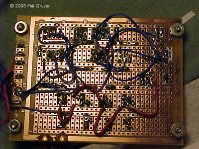
This circuit is shown schematically in Figure A - click here. Resistor R1 is really a series combination of two resistors, a 100 kiloOhm resistor and a variable 1 megaOhm resistor. Similarly, Resistor R14 is a series combination of two resistors, a 10 kiloOhm resistor and a variable 1megaOhm resistor. A square wave oscillator is generated with the 555 integrated circuit (IC). The frequency of the square wave is determined by the resistance of R1, and the capacitance of C1. This square wave is then integrated twice by the two op amps in the 1458 integrated circuit to come up with a sine wave. Because of the large values for R1 and C1, a very low frequency square wave is generated. The capacitance values used in the op amp circuits help to give a visible sine wave. This sine wave then drives the base of transistor Q1, 2N3904, which is then connected to four more transistors of type 2N2222. Each bulb is connected to its own transistor, and its own +9V battery. There are a total of six 9V batteries. Two of them were needed to bias the op amps and 555 IC. The remaining four batteries were used to ensure both that the bulbs could be turned on, and that the bulbs could be assured a long illumination time without taking up a lot of room for the batteries. The resistors R5, R6, and R9-R12 are used to scale down the output voltage of the 555 IC and to provide offsets to the op amps to ensure a positive waveform output. If no offset was present, then the oscillation would go positive and negative. The end result are four bulbs that vary in brightness sinusoidally with a frequency of about 0.25 to 0.5 hertz. The frequency of the applied square wave is varied by the potentiometer R1. The brightness is varied by potentiometer R14. Some tweaking of the resistors was necessary to reach the desired effect. Layout Description As can be seen from Figure B, the circuit was point-to-point soldered and connected to a perfboard with copper tracks. Although the parts list shows 18AWG wire, it is recommended that a higher gauge wire be used (say 22-28 AWG), for flexibility purposes. Epoxy was used to hold down the wires to allow for some strain relief. Table 1 lists the parts used in building this circuit. A little creativity, however, can reduce the total cost of parts. Table 2 shows the schematic parts list. Both are Word documents. | |
|
Meet the Authors Phil Gruver and Dave Rosignoli are telecommunication satellite engineers for Lockheed-Martin. Most of Phil's modeling efforts to date have concentrated on Macross and other Japanese anime (although he swears he has never built a Gundam). Dave has designed various electronics packages - most of which are now in orbit. Phil constructed the spacecraft model and campsite while Dave designed, built and tested the lighting circuit. Acknowledgements We'd like to thank the staff at D&J Hobbies, Talbot's Toys and Japantown Collectibles for their technical support and advice! |
||
![]()
This page copyright © 2003 Starship Modeler™.
First posted on 15 November 2003.
Last updated 11 December 2003.
![[Click to enlarge]](pg_logs_Fig32.JPG)
![[Click to enlarge]](pg_logs_Fig33.JPG)
![[Click to enlarge]](pg_logs_Fig14.jpg)
![[Click to enlarge]](pg_logs_Fig27.JPG)
![[Click to enlarge]](pg_logs_Fig23.JPG)
![[Click to enlarge]](pg_logs_Fig28.JPG)
![[Click to enlarge]](pg_logs_Fig29.JPG)
![[Click to enlarge]](pg_logs_Fig30.JPG)
![[Click to enlarge]](pg_logs_Fig31.JPG)