
|
By Clyde 'Zog' Jones - images & text © 2006 This is a project to build a "Print, Cut, Glue" Trek type shuttlecraft NON-kit. It isnt an exact copy of any particular shuttlecraft, but is a generic TOS type. A classic shuttlecraft can be made by altering the parts and proportions, of course. Thats the fun of scratch building models. If you dont have a kit of what you want, you can build it anyway. This technique is applicable to just about any subject - and is a good way to turn a paper/card model into something we're (maybe) more familiar with. |
![[Completed Model]](cj_pcg_d00007FLTV.jpg) |
|
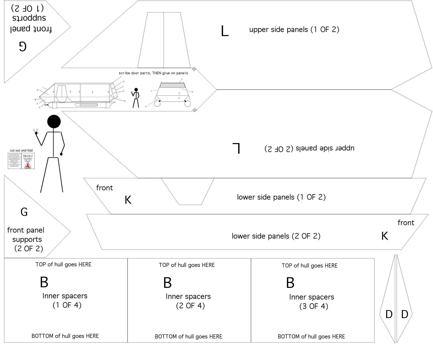
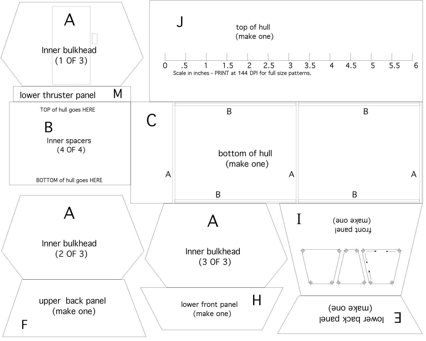
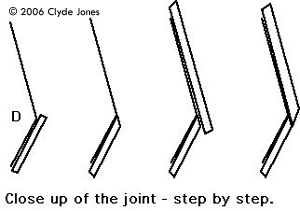
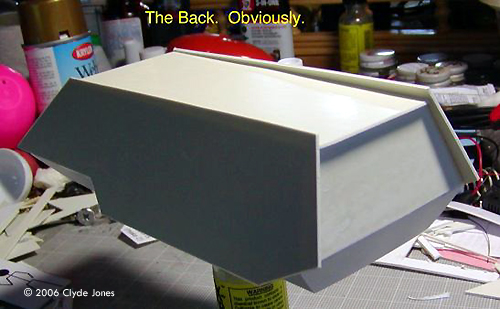
Instructions and Plans Image: Plans in PDF format (thanks to Frank Henriquez)Image: Plans, medium resolution, page 1 Image: Plans (med res) page 2 Image: Plans, page 1 (hi res) Image: Plans, page 2 (hi res) Image: Instructions (lo res - 72dpi) Image: Instructions (higher res, for printing) Image: .... then peel and stick on the styrene sheets. Image: Cut out the shapes Image: Building up the sides Image: Close-up of the joint, step by step Image: Back detail Image: Lower back Image: Back, with out the thrusters Image: Hull is basically finsihed Image: Adding detail Completed Model Image: Front/right viewImage: Right side Image: Right/rear |
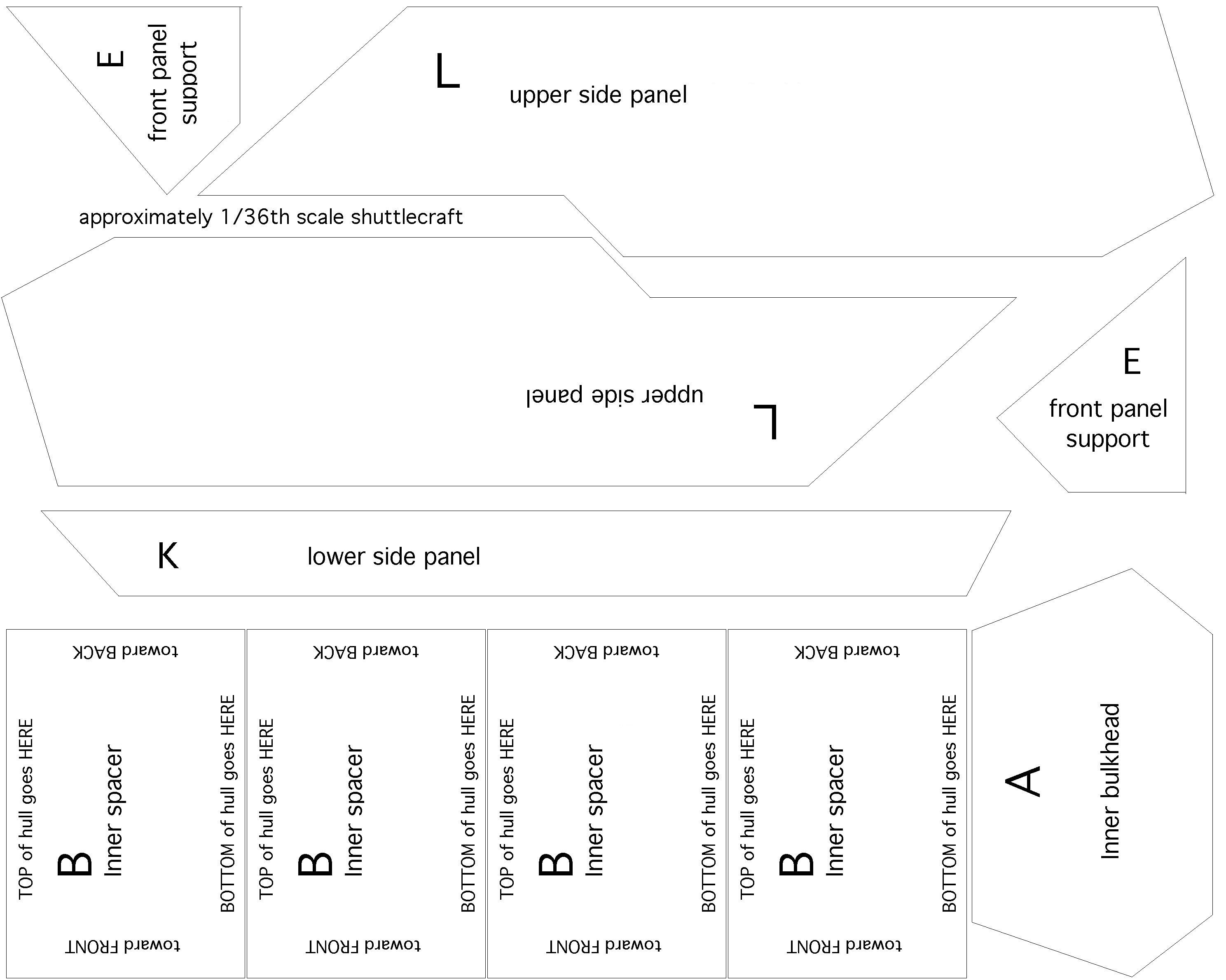
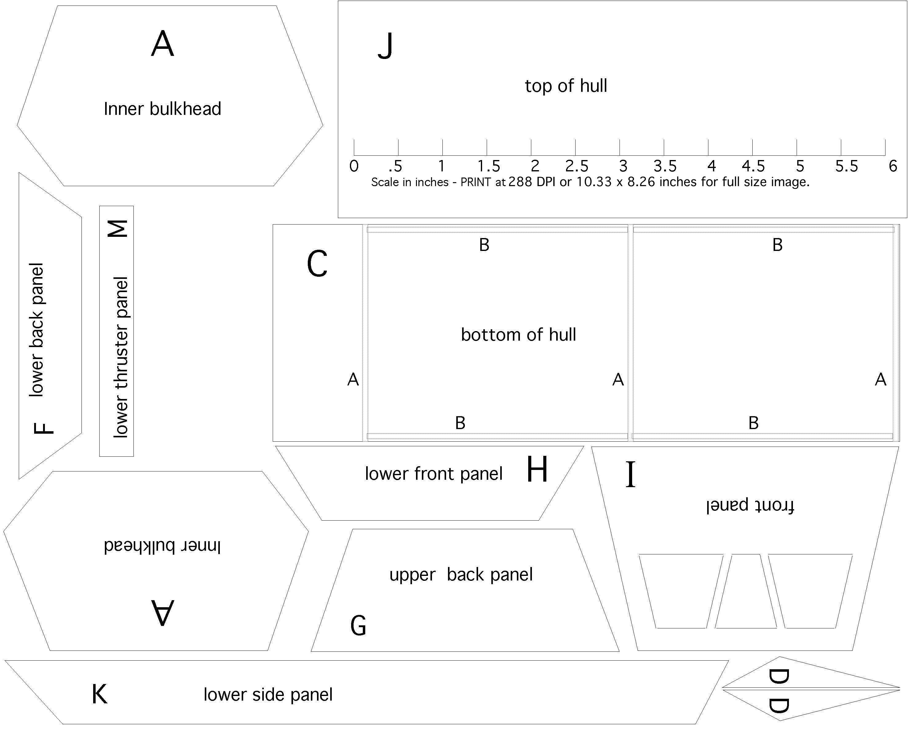
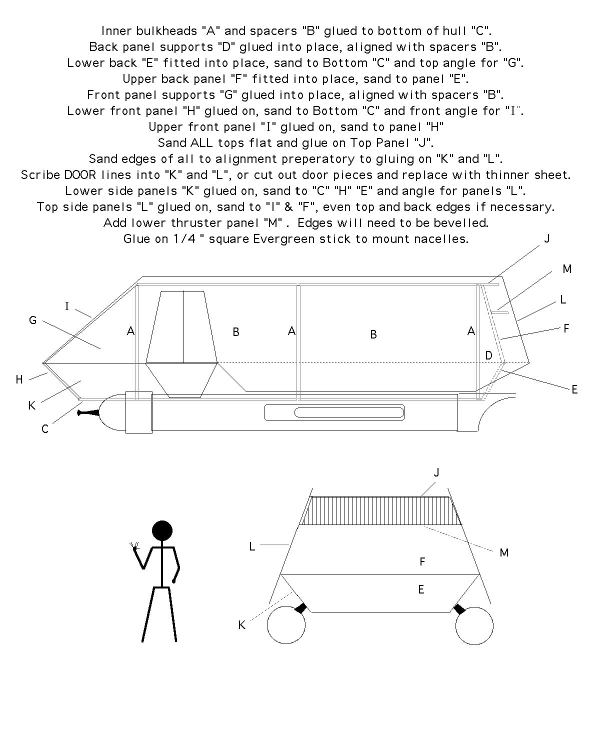
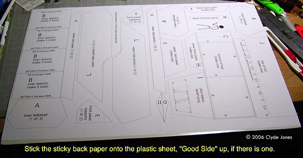
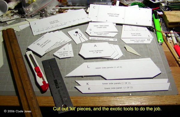
What you need, aside from a computer and printer, is a couple of sheets of AVERY or equivalent 8 1/2 x 11 inch self stick label stock, ( a full, un-die cut sheet, in other words) and a few square feet of styrene sheet stock, plus the usual model building tools. The label stock can come from the local office supply store. The styrene can come from the hobby shop (Evergreen) or hardware store - FOR SALE or OPEN HOUSE signs for instance. Personally, I like the OPEN HOUSE signs because they are made with thicker plastic. I also use a liquid cement like Tenax-7R or SC-125 or one of the Micro-Welds. When the joints are touching, glue is allowed to run into the joints, and a little pressure is applied the softened plastic at the joint squishes out a bit forming a very solid joint. On an injection molded kit, lots of work goes into making sure that all dimensions are precise and everything fits exactly. (Well, thats the theory anyway.) On a scratch build project like this, where each version is a one off model, things arent quite that precise. These plans are made as carefully as my time allows, and fiddled with to be pretty close. But not necessarily perfect. So you will have to do some fit in place work to make parts fit exactly. The bad news? You will have to do a good bit of sanding to final fit. The good news? Done carefully there are no visible joints - the finished model of mine is not only solid, its air tight. Small vent holes MUST be drilled in the void spaces or closed volumes of the model so solvent fumes can escape, rather than being stuck inside the model and softening it. Getting Started If you are familiar with the Scribe and POP method of cutting out parts, and have done some scratch building, the included HOW TO sheet should be all you need. If not... Lets start at the beginning. Please notice that the test model shown in the accompanying pictures was built with a different layout and numbering of the parts. These instructions and the downloadable patterns use the proper and matching numbers. The actual construction photos may show different part numbers. First, download the patterns. They are done in 288 DPI resolution meant to be printed on (US) standard 8 1/2 x 11 sheets of sticky back label stock. Please do so. Then actually stick the sheets to blank styrene sheet stock. This gives you a firmly attached set of patterns for cutting out the parts. Not to mention labeling them. The finished model is about 1/35 th scale as laid out. To change the scale, change the printing size. There is a printing size scale on one layout sheet that may help this. For instance, to make a 1/72 nd craft - reduce these plans by 50 % or there about. Of course, if you enlarge these printing patterns to say 1/24th scale, they will no longer fit on a standard sheet of paper. You will have to rearrange them to suit. Once you have these plans printed out you can use a sharp Xacto or OLFA knife to scribe around all the parts prior to popping them out. The Scribe and POP! technique is described in a separate article. On the first sheet, with the long parts like the upper and lower sides, you should drill TINY holes where there are small circles and cross hairs. That will give the later cuts and pops a good stopping place. Otherwise the popped separation may continue on into the part. Then make the long horizontal cuts separating the major sections. Continue those lines to the edges of the sheet for now so you can pop the long lines where parts adjoin first. Where there is another part that interrupts the long straight cuts, just stop between parts, and cut an in between joint so you can separate the parts. The end cuts can be made more easily if these long parts are already separated out. When cutting out the B parts, cut along the RIGHT end first, then the top and bottoms. Then separate the parts. Then cut around and pop out the smaller wedgie bits. Parts D and G can be filed or sanded to exact profile, or just popped since the dimensions are important, not the finish. If you wish to have an open door, or to have an inset door made with separate pieces, you should cut out the door openings when the side pieces are separate. If not, you can most easily scribe the doors at this point. On sheet two - with the front and back panels and hexagonal bulkheads, cutting may be easier if you follow this sequence. Theres a nice straight line between the C and J that can neatly separate out parts J A and M. Part B can be popped out next starting the first cut UP from the space between B and A along the LEFT edge of C to the edge of the sheet. Then scribe and pop off section B. Now part C can be scribed and popped off. The other panels on the sheet may take a little work but try removing E from I then remove H from A and then F from A. Finish separating all the panels, and sort by letter. Construction goes pretty much by alphabet here. Part C has a layout and assembly guide for the parts A and B printed on it. You can refer to this and glue the parts to the OTHER side of C where there is no sticky paper. |
|
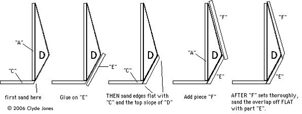
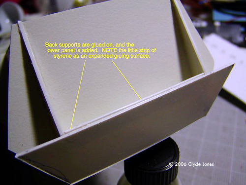
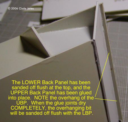
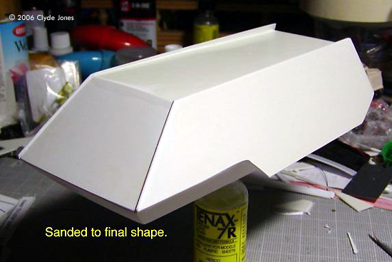
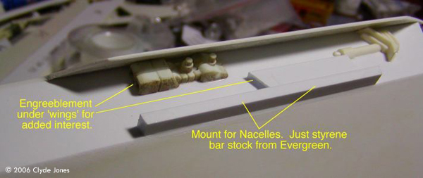
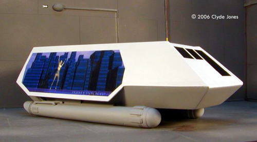
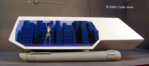
Construction Start with the A panel closest to the back of part C. Next to it goes two parts B - the combination of A and B joined together keeps them from folding flat onto C - handy that. REMOVE the sticky paper from the middle part A, and glue it to the first parts B. Thats a complete open topped box. Glue on two more parts B. Then glue on the last part A - the one with the door opening. If you are going to have an interior this door can be cut out BEFORE you start assembling. Please make sure that the parts B are centered on the keel of the ship as you go - that's part C. Some rubber bands may be carefully stretched around this assembly to help squish the joints together solidly, but make SURE that those rubber bands dont distort the basic shape. To be safe, once parts have begun to set and wont pull apart to easily you can take part J and SET it on top of the model and rubber band that in place to seat parts A and B firmly in place on C. Again, make sure that the basic form is not being distorted by the pressure of the rubber bands. Let this assembly set up solidly before going on to the next steps. Theoretically, all the edges of the A parts should form a couple of nice flat planes for the side pieces to glue to. Thats theory. Slight variations in cutting or gluing may keep these edges from forming one flat plane. NOW is the time to correct that. If you cit the parts A a bit wide so the lines show, you can tape a large piece of sand paper to a FLAT surface and gently sand all the edges of the A parts together so they DO form a flat surface. Be careful to keep the lines and proportions even so all the joining edges are straight. Also try and wet sand the edges. Styrene dust may not be too toxic but you dont need to breath it. You should now have a very solidly glued-together basic form of the ship. You may now peel off the paper on the remaining parts A. Add the parts D to the back of the ship, aligned with the B parts and centered on the back A wall, and let them dry. These parts will support the back panels of the shuttle. Once parts D are SOLIDLY set, you can attach part E - the lower back panel or bulkhead. FIRST carefully sand the back edge of C - the keel or bottom - so that it forms a flat plane with the lower parts of E. This part is intentionally a bit tall so that it can overlap the bottom of C and go past the peak of parts D. Once its COMPLETELY set sand it off even with the bottom of C and with the TOP SLOPE of D. For a larger gluing surface for part F, you can glue a strip of plastic stock between the C pieces at the top of piece E. Now attach part F overlapping the top of E and sticking up over both D and A. The sanding on E should make for a nice flat joint between the two parts. With liquid cement and a bit of pressure, it can form a virtually invisible squish joint. Once F has set COMPLETELY sand off the bottom flat with part E. Sanding while the joint is still soft will cause tearing and gouging of the softened styrene which will make a bad looking joint. Let em set. This process is repeated at the front of the craft with parts G H and I. First attach G and let it set. Then attach H with a bit of overlap on the peak of G and bottom of C. When thats REALLY dry and set, sand it off even with the bottom of C and the TOP slope of G. Attach I with a bit of overlap onto H and sticking up a bit over the top of G and let it set. Sand off the overlap with H. Remember - if you want open windows in the front on part I cut them first. For the window pattern given, first drill out the corners of the windows, then scribe the sides moving your knife FROM the corners TO the middles of the sides. This prevents the scriber or knife from going past the corners and making a bad POP separation. You may also want to make scribes from opposite corners crossing like an X and take out the window openings in pieces. If you are going to paint the windows or make a decal like I did, then you dont need to worry about that part. Now carefully sand all the tops flat and even (if they arent already) and attach J. Overlap part I on the front a bit and leave the rest on the back overlapping F to form the top of the Impulse Engine. Sand the front of J even with I. In spite of all the planning, figuring, careful cutting, and gluing, doing something with a hexagonal cross section isnt easy. So this is where the sand until it fits approach comes in handy. Parts E F H and I are deliberately a bit wide. Why? Because trying to figure the dimensions out with total accuracy drives me nuts and because no matter how well I calculate, reality has a way of disagreeing with me. Thats called engineering. Which leads to the Cut and Try approach. Or Sand until it Fits method. The sides of all the A pieces, and E F H I and J should form a set of flat planes so the side pieces will fit nice and flat. Usually, they dont so were back to our sheet of sand paper on a nice flat surface. Keeping an even pressure gently sand all the edges until each sides gluing surfaces are even and flat. I attached the parts K - Lower Side Panels - next, let em dry and then sanded em even with the keel C and with the slant of the top sections B and so on. Then added the Top Side Panels L. L should be left sticking up over the body of the shuttle for a bit of style and to echo the original shuttlecraft. The fronts of the L panels can similarly be left sticking out a bit. The Lower Thruster Panel M goes on last, sanding its ends to an angle matching the slant of parts L. Details, Details... The body is now pretty much finished. You can paint or decal in windows in the front of the craft if you havent already cut them out - if you wish inset windows or to add an interior. (If you do add an interior, that should go in before all the walls L and front panel go on.) I used a set of spare nacelles left over from another project on this ship. With this size of shuttle, the PL Enterprise nacelles work quite well. If you change the scale of your shuttlecraft you may have to scratch build your nacelles or borrow ones from another size kit. The attachment is just a couple of chunks of 1/4 inch Evergreen strip stock glued to the side of the hull, even with the bottom. Greeblies went under the wings on the sides just to keep them from looking too barren. Since some of the nacelle halves have gaps for anchoring to the usual PL Enterprise Nacelle supports which I dont need, I used parts with NO slots, which means a bit of extra work. Mainly cutting off the locating pins and gluing a few strips of thin Evergreen stock into some of the nacelle halves to provide both locating surfaces, and a greater surface area for gluing. Do you want to modify the design? GO AHEAD! Say that you want a rounded lower front like the TOS classic. O.K. Make the bottom of parts G round. Carefully sand the front bottoms of parts K to match that curve. Cut C a bit short, or put it on LAST building up parts A and B from the TOP, part J, and pre-curve it by bending the front part around a small round object like a pencil. Do you want it shorter? Shorten it! Just take an even amount out of all the long body parts - C J K and L and TWO of the spacer bulkhead parts B. Dont like the wings as they are? You know what to do. ![[Done]](cj_pcg_05LSV.jpg) Finishing Just to be different from all the TREK type shuttlecraft out there, I made this into a Klingon Low Rider. Huge murals on the sides (as advertisements for Koloths House of Gak) and a bit of extra length. I plan to do some detailing in Gold - like the nacelle end caps and a few other parts. The murals are decals done up on JetCal decal paper from my own artwork. And I may add side windows later.... Now: What kind of shuttlecraft are YOU going to build? |
![]()
This page copyright © 2006 Starship Modeler™. First posted on 6 March 2006.
![[Stick to the plan]](cj_pcg_288_DPI_page_1_lil.jpg)
![[Please click to enlarge]](cj_pcg_001first-print.jpg)
![[Please click to enlarge]](cj_pcg_004basicBOX.jpg)
![[Please click to enlarge]](cj_pcg_009Bodyroughed.jpg)
![[Please click to enlarge]](cj_pcg_016nacelles.jpg)
![[Please click to enlarge]](cj_pcg_018structurallycomplete.jpg)