Snapshot |
|---|
| Scale: 1/144 -- approximately 3"/ 76mm in diameter when assembled. |
| Parts: 53 resin + 1 clear vacuform (with buck). |
| Instructions: Illustrated assembly & paint guide, in English. |
| Decals: ALPS-printed waterslade, markings for one machine (4 different names). |
| MSRP: $99.95 USD in 2011. No longer in production (as of 2022) but occasionally available on the secondary market. |
| Overall Rating: See review. |
The Stargazer Aries was my first venture into resin models, but the resin guys are the only ones making accessible kits of the "2001 - A Space Odyssey" ship models, so it's either "their way or go scratch." Well ... their way it is. ( As of this 2022 update, this kit is still the only 1/144 offering, though Moebius has recently released a 1/48 version in styrene-- Ed.
I read the preview article posted on Starship Modeler and ordered the Stargazer Aries. On the whole, I was very pleased with the detail of all of the parts. The instruction manual was really pretty good, right up to the point where you really got into the interior detail. Then, it just stopped.
So, I thought I would toss my "two cents in" to those of you thinking about the kit and wondering "how do I get there from here?"
Click "+" to expand text and "-" to hide.
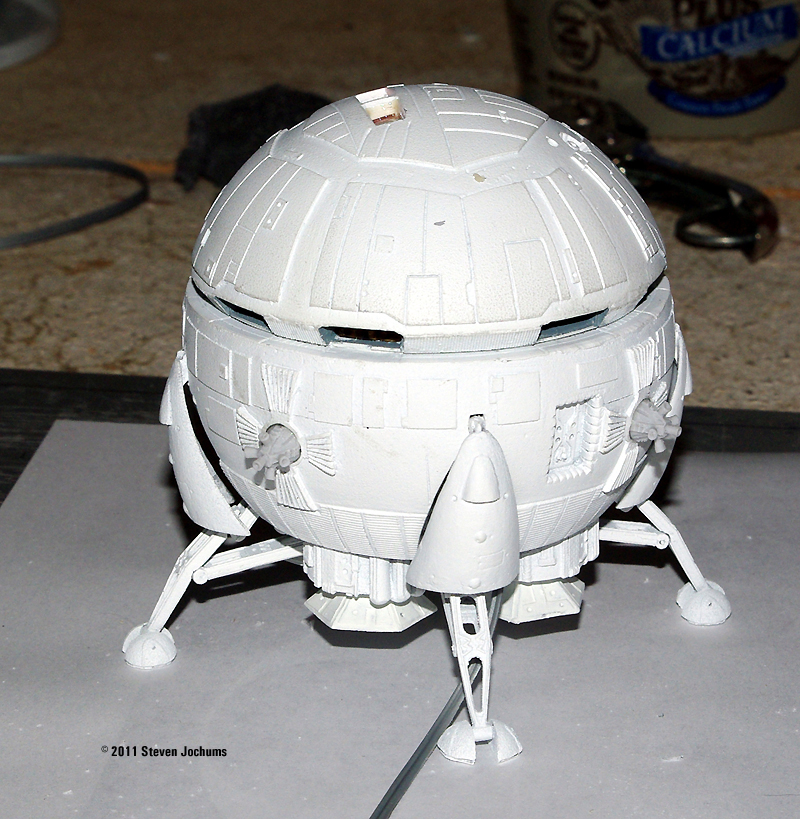
We'll pick up where the interior floor disk gets set into the lower hull, after the assembly of the landing gear. I wanted to allow the gear "articulate," so I did all of the drilling and installation of hinge wires - not easy, but not ridiculously hard either. This means the gear doors needed to pivot a bit - something that Stargazer says you can get from the "friction fit between the hinges and the openings in the lower hull." Right ... more info on this later. For now, the gear doors stay off.
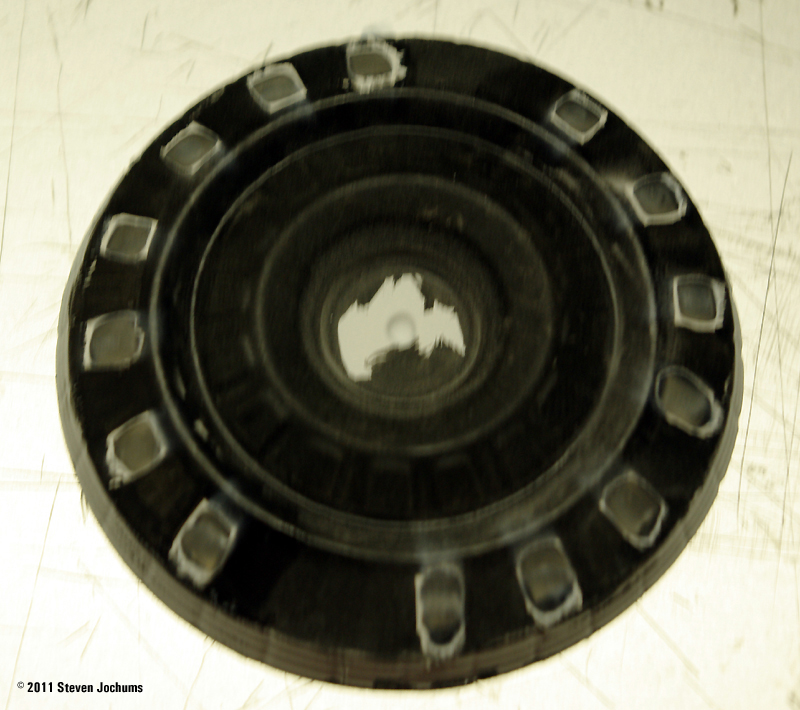
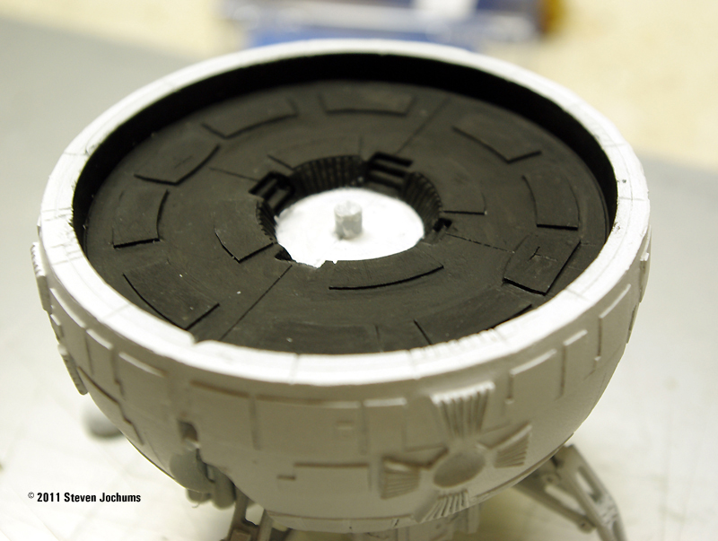
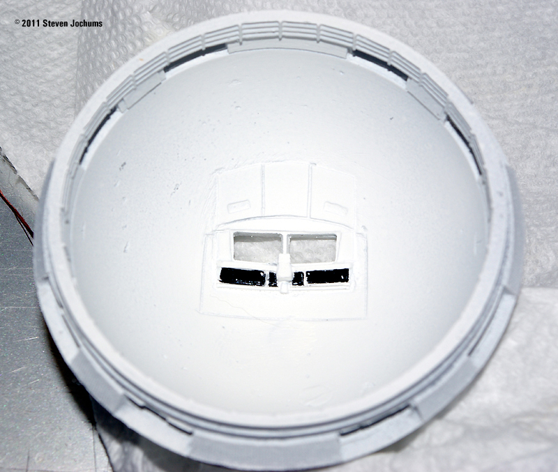
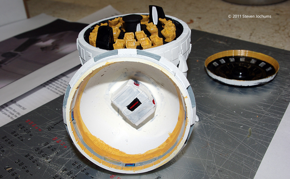
Fitment of the floor disk into the hull is not straight-forward. While there is an alignment slot and a ridge running around the inside of the lower hull for it to "supposedly" rest on, the disk did not want to sit flat. It seemed to want to slip down one way and then another. There are "out-of-round" problems with the top edge of the floor disk, which is what creates the concentricity issue. A little strategic sanding and the floor disk will sit, but not tight. I set the disk with ACC (superglue) and then finished off the seam with light epoxy.
Looking at the Stargazer instructions, they do note that you must choose between a full cockpit, with two rows of crew seating or the full passenger interior with the vacuum-formed plastic ceiling. I choose the latter, but I also wanted to try to light the cockpit and the passenger interior, so all of my assembly and painting choices were based on that goal.
The entire sub-assembled model was painted in Primer White before doing anything else. The primer white, with a bit of charcoal weathering looks as close to the movie model as need be, so it was a good place to start. This white primer coat was also included on the inner surface of the vacuum-formed main cabin ceiling, as a possible background for light distribution. We would end up dealing with this again, later.

^ For now, the gear doors stay off.
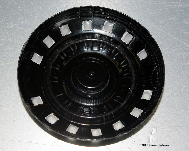
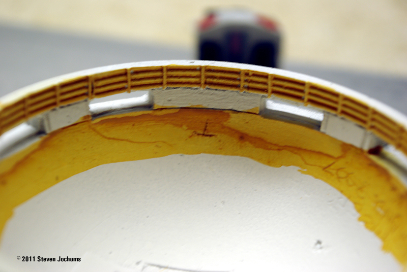
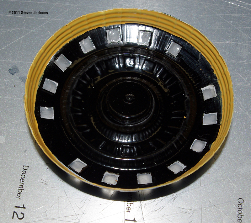
After snagging a few Aries interior stills from the movie DVD, I can faithfully report on all of the colors of the main cabin details. The square light panels around the outer ring of the ceiling dome were masked off, so light could come through the white primer coat. These are the light panels for the cabin in the movie. Then, the interior-facing surface of the ceiling was sprayed gloss black, so it appears to be black leather or vinyl, as in the film.
The passenger seats, the wall padding around the perimeters of the ceiling and upper hull are all "Saddle-colored." The seats appear to be leather, and the walls appear to be padded and colored to match the seats, but look more "cloth covered." I used an actual Saddle-colored acrylic leather dye to colorize these areas, but there are also paints that will work just as well. Also, knowing the leather-colored portion of the ceiling would need to meet up with the upper hull surface, I applied some Saddle-color to the areas above the side windows, to help with the transition if fitment of the ceiling dome was troublesome. The areas between the side windows are a light grey. Testors Camouflage Grey works well here. I did not paint these areas until much later in the build.
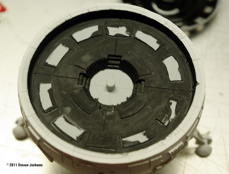
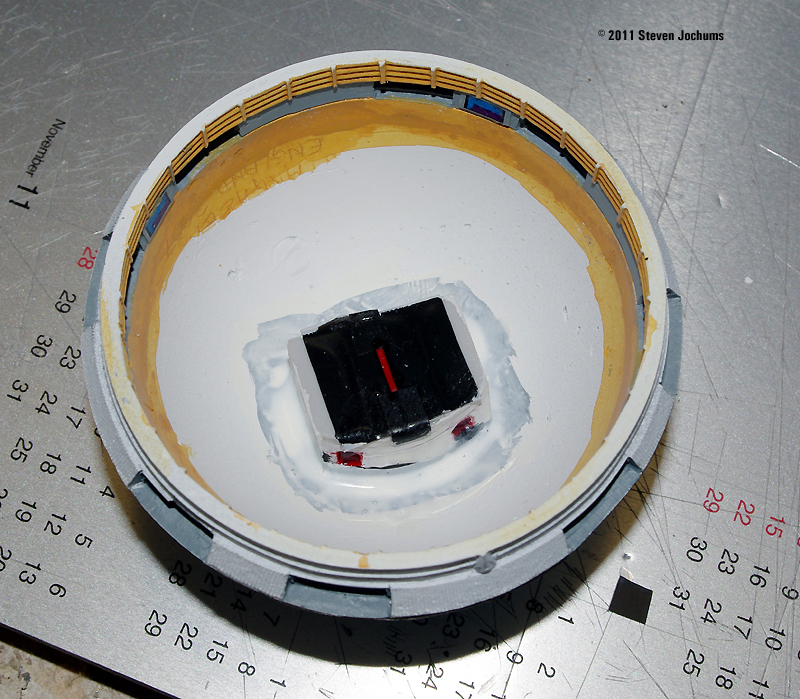
The main cabin floor is black carpeting (flat black). The Zero-G toilet exteriors are gloss black, and their doors are gloss white. The central floor circle around the bottom of the elevator core is supposed to back-lit, so I painted it gloss white. The elevator tube proper is flat black on the outside with a gloss white door.
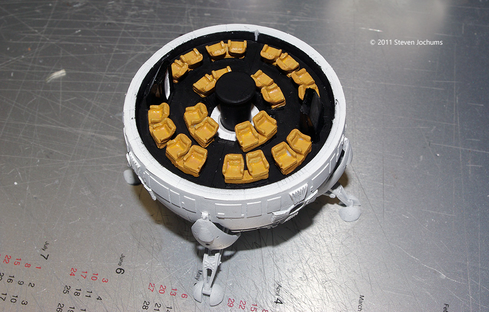
^ Passenger cabin.
With trying to light the cockpit and the main cabin in mind, I looked at these scenes from the film again. As you may recall, everything looks red in the cockpit, but everyone's uniforms were white when they appeared in the main cabin. This means the cockpit used red lights, just like a photo darkrooms or astronomers do, to prevent light sensitivity problems with the eyes.
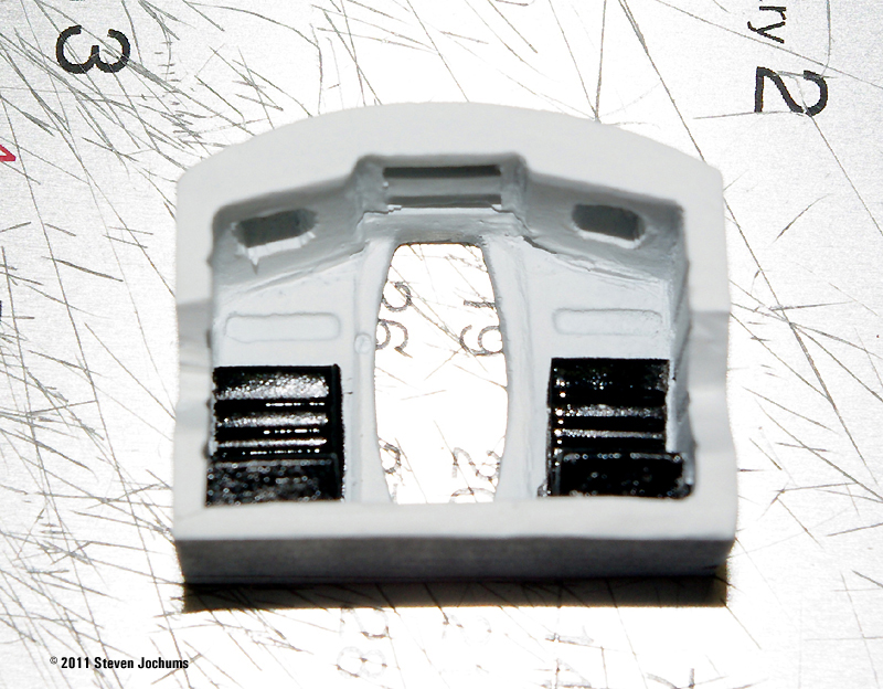
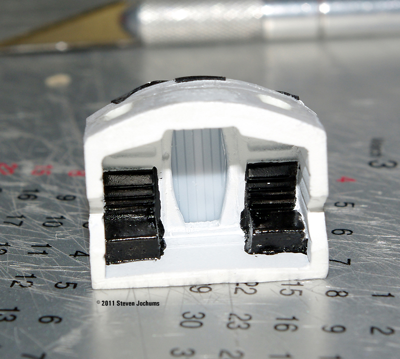
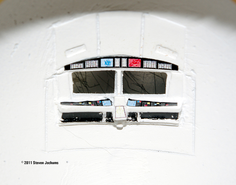
To get the effect, I opened up the two "window-like" areas above the seats in the "short" cockpit segment, to create two square windows. The cockpit segment interior is painted flat white, except for the seats which are gloss black. The instrument decals were placed onto their locations in the "nose" of the upper hull, and to the sides of the short segment above the seats. The lower surfaces of the forward instrument panel were painted flat black to match what is in the film.
A rear cockpit door was fabricated from a piece of Plastruct 0.010" white styrene "car siding," which has a nice grooved pattern in it, like all the other doors on the Aries. Once cemented on, the rear of the door was masked to allow only a ribbon of light to show through the white plastic. This mimics the door lights seen in the film.
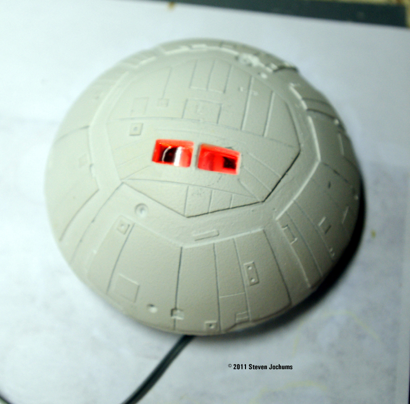
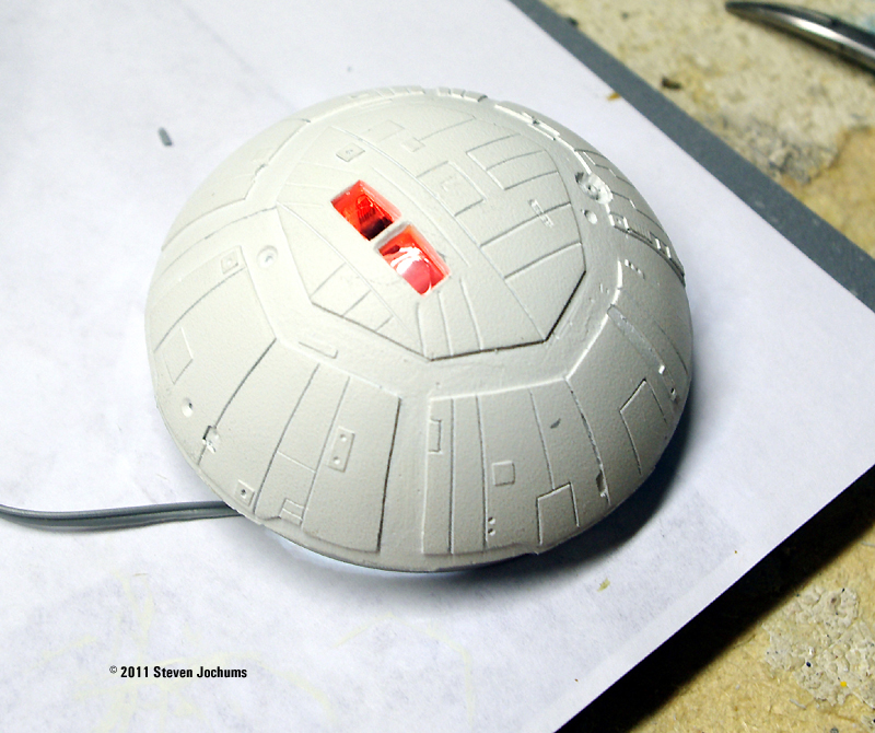
The two square top windows were filled in with Testors Clear Window Cement, which dries clear itself and is used to fabricate windows on many small models. After the windows dried, they and the door ribbon were over-coated with Tamiya Clear Red acrylic. This made sure that when the white LEDs hit them, only red light would come through. All cockpit instrument decals were placed at this time. (IMG5659)
The clear plastic material furnished with the kit was far too thick to easily work with, so the forward cockpit windows were made from 0.010" clear sheet plastic and cemented into place with the Testors Window Cement.
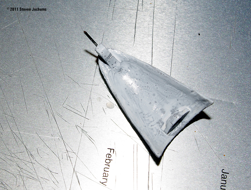
The completed short cockpit had to be cut with V-shaped openings on both side walls in order to locate and center it over the instrument panel. Once the alignment looked good, the cockpit section was set onto the upper hull with epoxy. Once the epoxy cured, two coats of flat black for light-proofing, and two coats of flat white for reflectivity were applied to the outer surfaces.
^ Major assemblies.
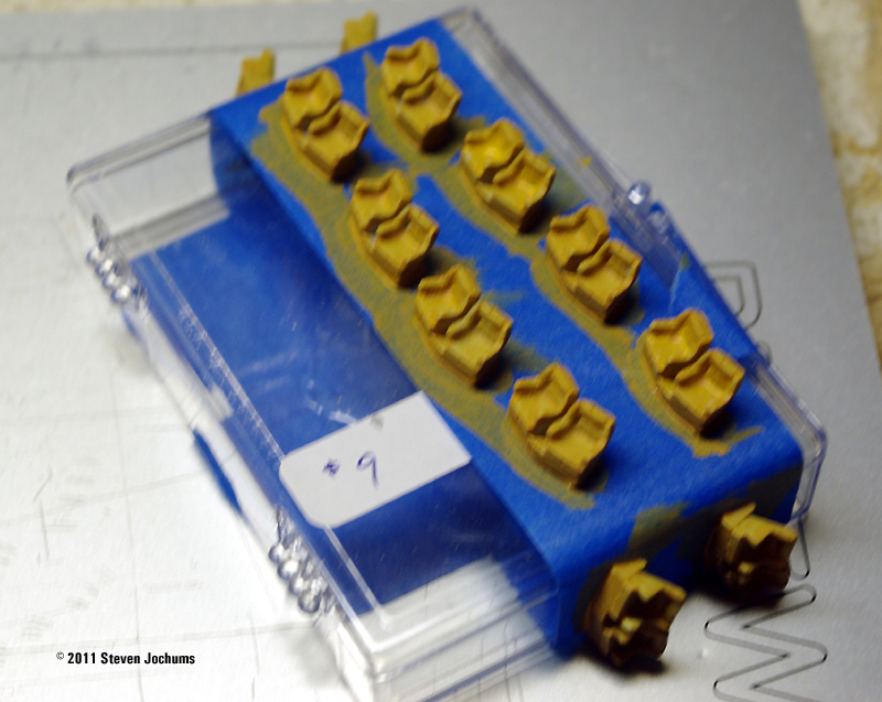
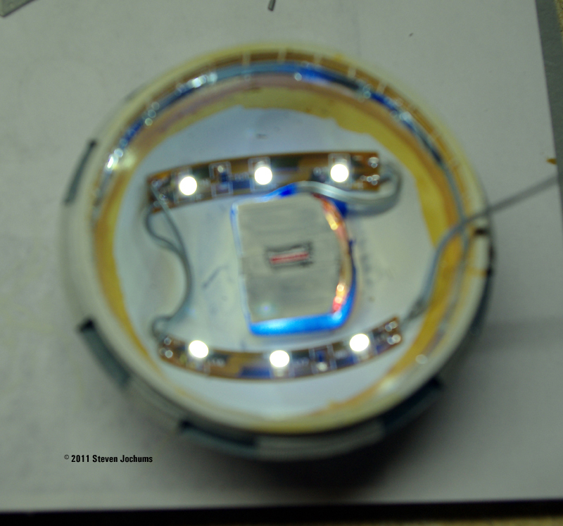
The mechanism for the lighting system was the Paragrafix E-Z-LED system, also available from Starship Modeler (at the time). The strips of pre-wired, surface-mounted white LEDs, that can be separated into "blocks" of three LEDs, each with their own current-limiting resistor, solder terminals at both ends and a self-adhesive backing to hold it in place. I came to find that the two red windows in the cockpit top were exactly the distance between two LEDs on the strip. But they come apart in "threes." Now, the challenge was to figure out how to get even illumination into the main cabin and still hit the two red windows on the cockpit.
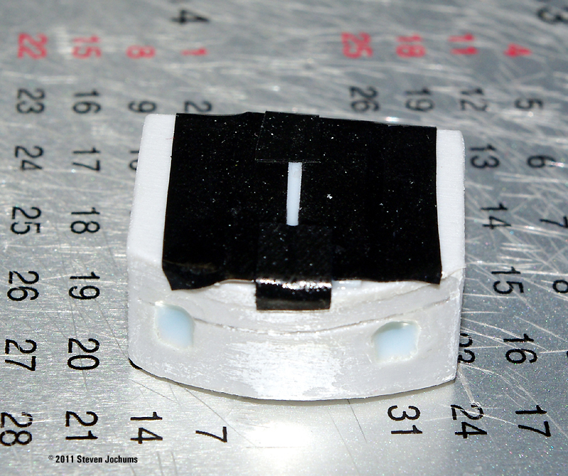
I decided to use two normal three-LED segments to do the main cabin light, and a "truncated" strip of two LEDs with a resistor on the cockpit roof. This required that the "trace" of the two-LED segment be shunted together, so to close the circuit for current to flow. Normally, the third LED in the set closes the circuit. Power comes into the first full segment, goes to the second and then to the two-LED segment.
The full segments were stuck to the interior surface of the upper hull, on either side of the short cockpit. The cockpit LEDs were positioned over the two red windows and fastened with white vinyl tape, to prevent movement and reflect light from the other LEDs.
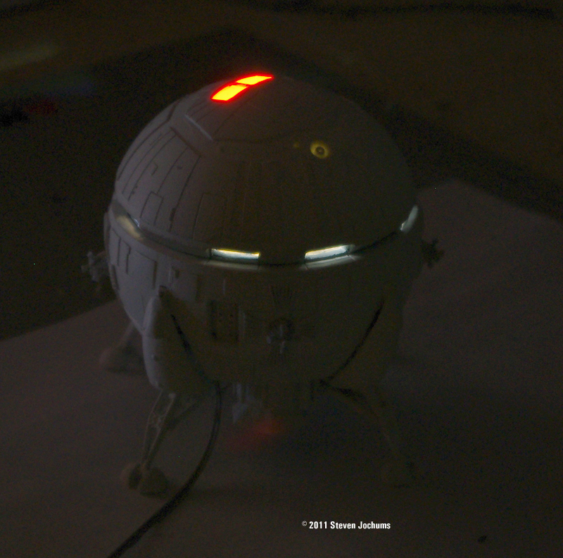
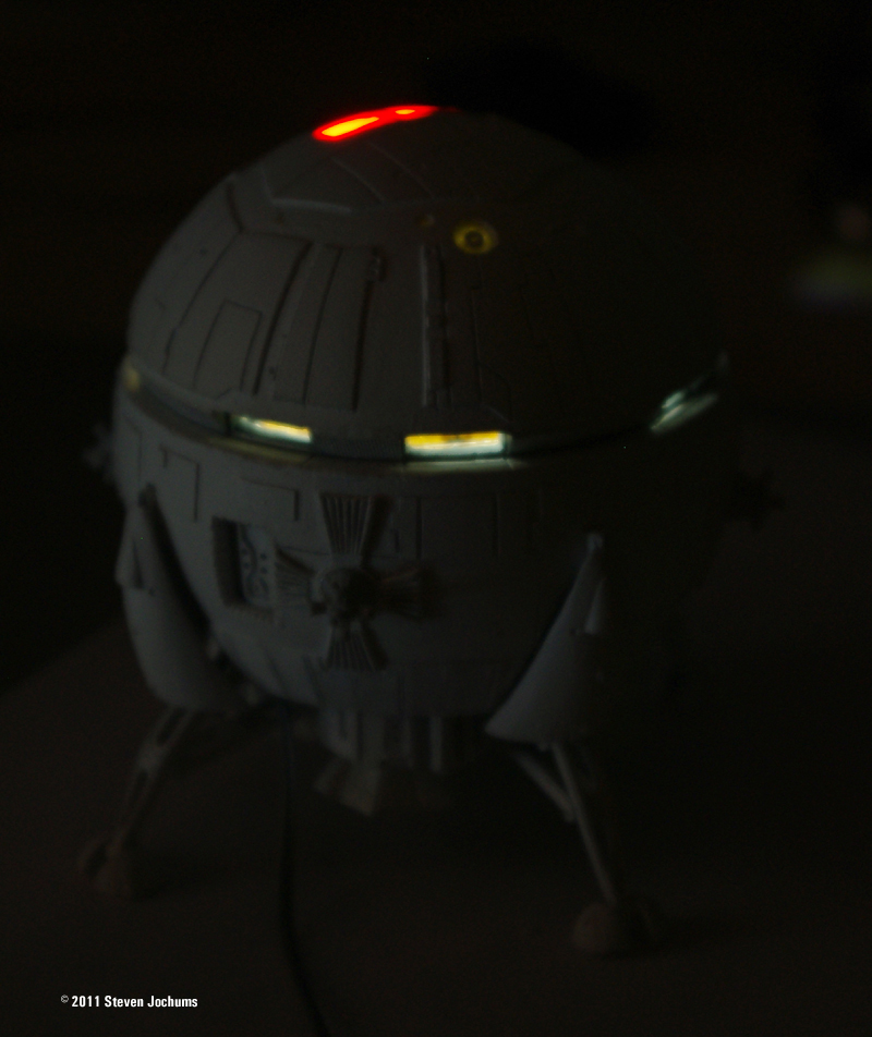
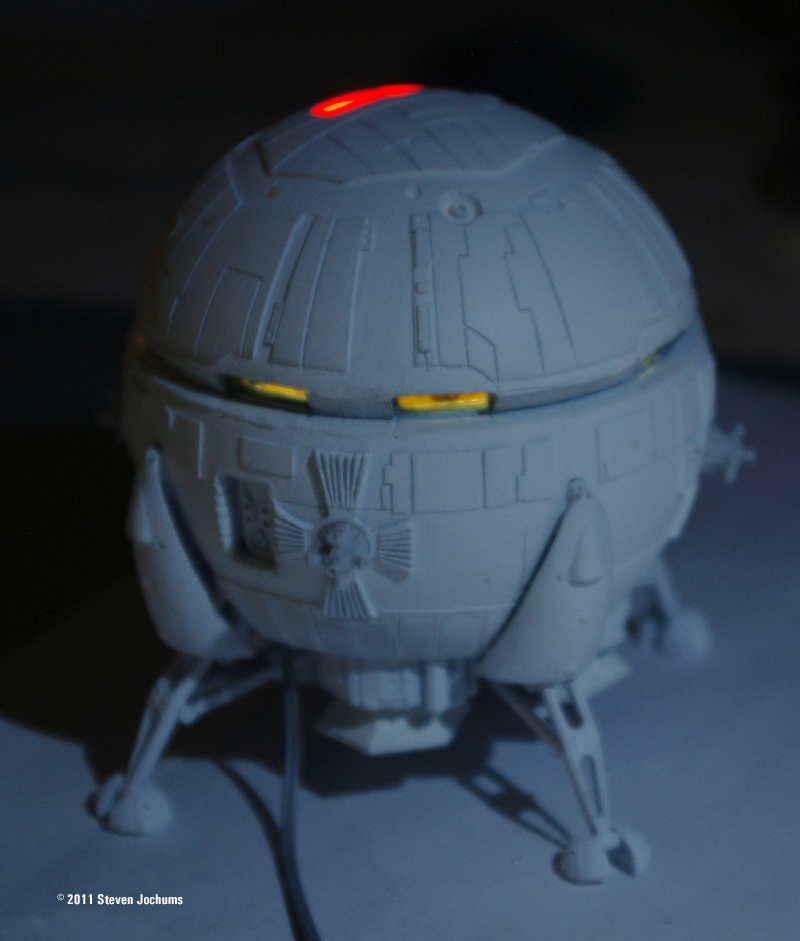
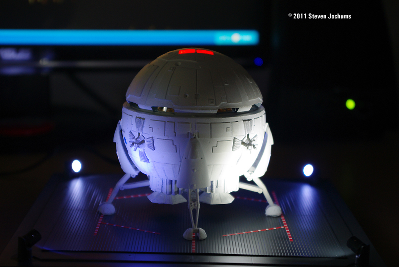
The red light effect in the cockpit turned our great, as you can see!
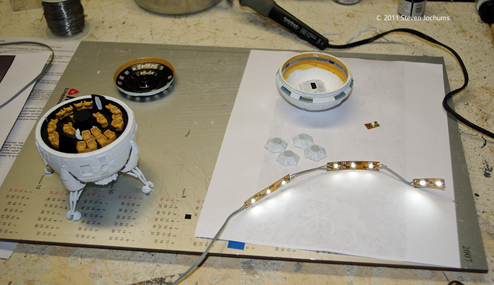
^ LED strips (the cockpit lights have been chopped down).
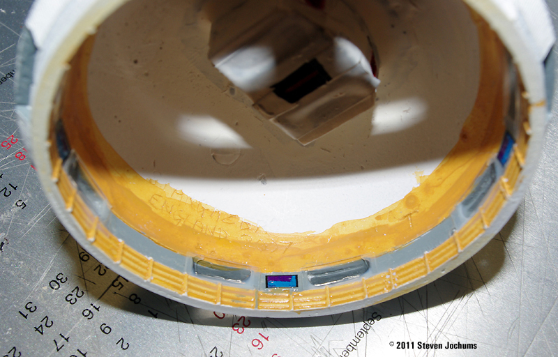
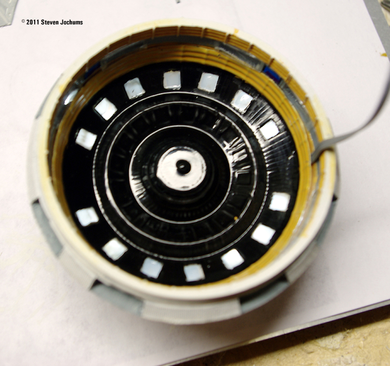
The ceiling dome was then "trial-fitted" into the upper hull. That's when I found out the white primer did not let much light through. So, I placed a small buffer wheel onto the Dremmel and buffed the white paint off of each of the light panels. The nice part is that the buffer wheel also "frosted" the surface of the plastic, which made the light panels look even better.
The side windows were put in next. Small sections of 0.010" clear plastic were cut to size and laid into their location, and locked in with Testors Clear Window Cement. Since the top edges of the windows were exposed above the window line, the ceiling dome actually rested right on top of their edges when finally installed. The dome was set in place with Testors Clear Cement. The TV screen decals were also put into place at this time.
The thin gray lead wire was brought out from behind the ceiling down so that it exited the cabin behind one of the toilet enclosures. A small hole was drilled into the disk floor behind the toilet, and the wire fed through to exit the landing gear bay below.
Now, what about those gear doors? Well, mine never really fitted into their slots with enough friction to really hold them in place. So I decided to give them a bit of assistance, by drilling into the tip of the door and inserting a section of solid 22 AWG copper wire, then drilling a corresponding hole into the hinge slot in the lower hull to capture the other end. The wire is soft enough to bend when the door is moved, but holds it in place quite nicely.
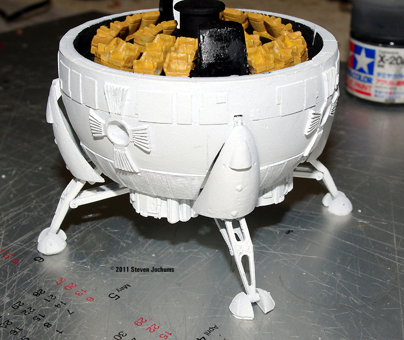
When I tried to fit the upper hull, with lighting and ceiling dome in place into the lower hull, I found that the round "dimple" in the center of the ceiling dome made contact with the central elevator core and would not sit closed. After carefully removing the dome section with an X-acto knife, the Aries 1B came together.
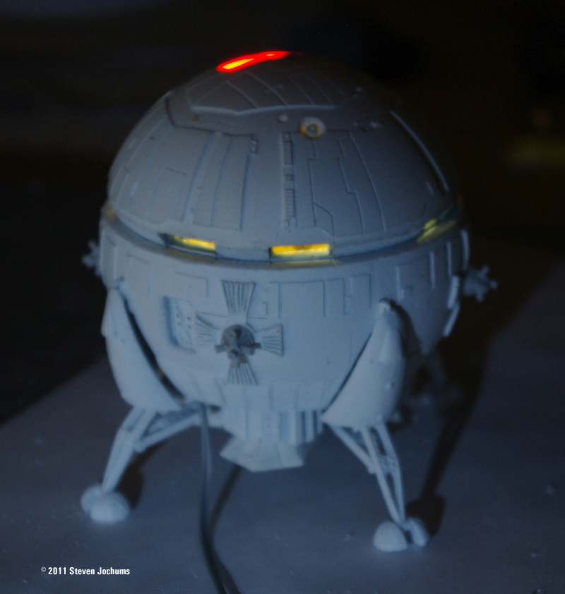
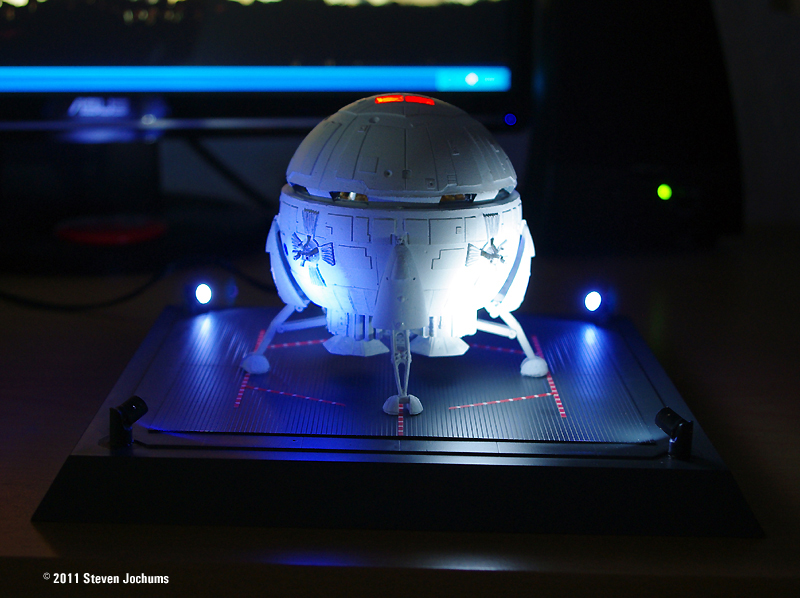
Now, for a trial run with power ... The results are quite good, as you can see.
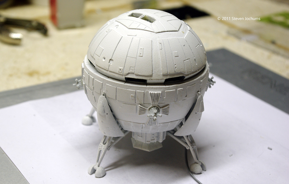
^ Everything together.
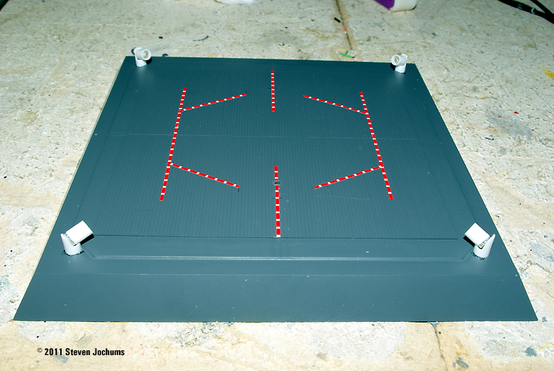
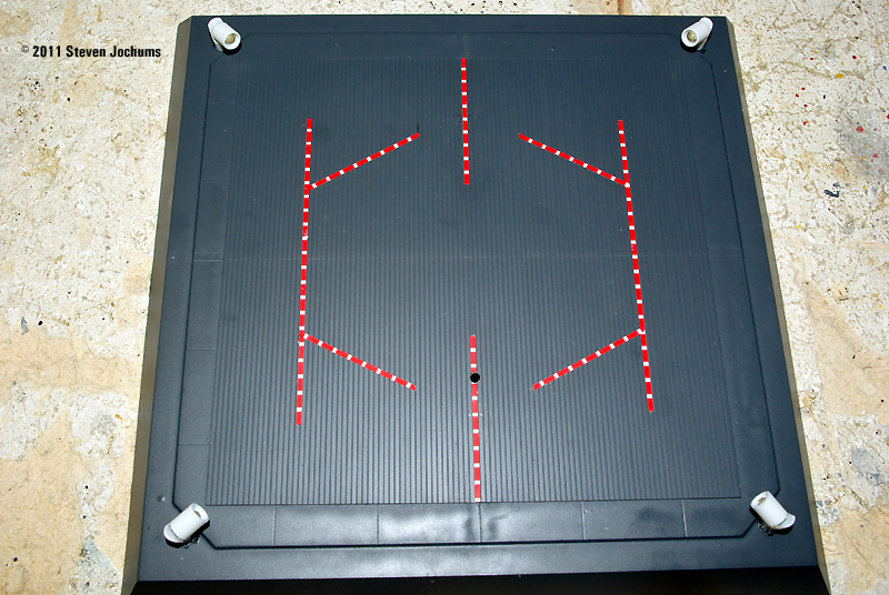
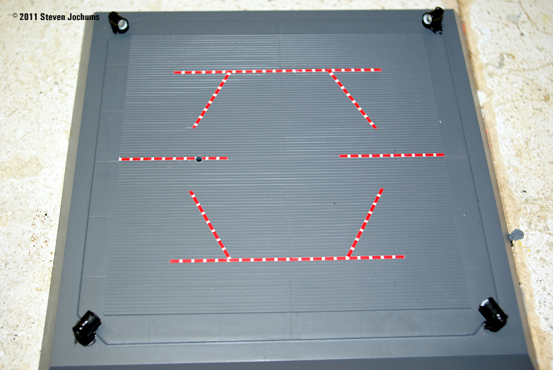
The Aries now needed a fitting display base. I had a square base from a Revell 1/96 scale Saturn V that looked just about right. Looking at the landing pad from the movie (Clavius Still), I went about creating a "version" of the pad, using V-groove sheet styrene for the surface, striping tape for the markings and with LED lights at each corner to illuminate the Aries. The overall color is German Grey.
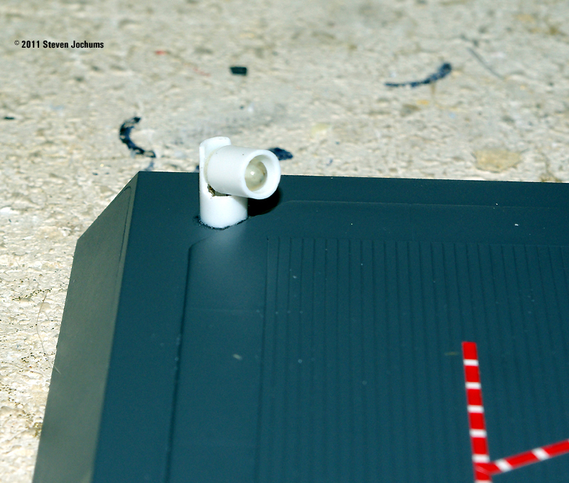
The LEDs were "refugees" from outdoor solar lights, whose circuits were bad or the housings broken. The solar lights ran off of two 1.5 V "AAA" batteries, so a 3.7 V "refugee" Nokia cell phone power supply worked out just right. The supports and barrels for the lamps were hand-fashioned from Evergreen Styrene ¼-inch tube, each section about 3/8 inches long. One section was the "barrel" for the LED lamp, and the other was the support. An L-shaped notch was cut into the top of the support to hold the barrel and tip it at about a 30-degree angle. The supports sections were first cemented to the display deck, so that the notch "looked" towards the center.
Once the cement cured, a hole was drilled through the center through the display deck. Then, the LED was inserted into the barrel, the LED leads were bent downward to pass through the support, and the barrel was cemented into place using Testors Window Cement, as not to harm the LED itself. Once hard, more Window Cement was placed into the cavity of the support tube from underneath, in order to "lock" the LED and isolate the leads. The outer surfaces of the lamps were first done in Flat Black for light proofing, then in German Grey to match the base.
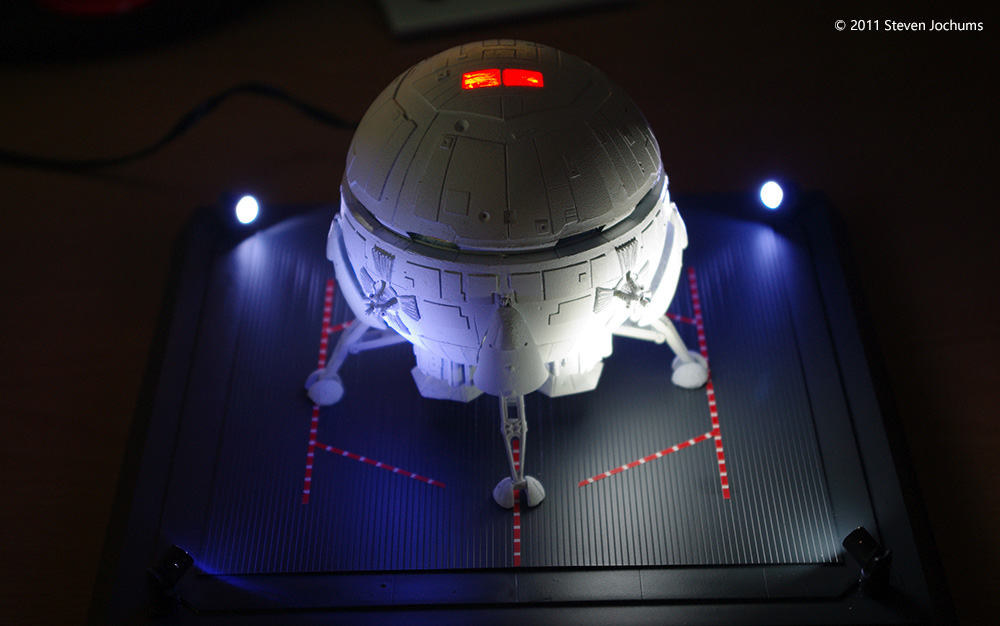
Now the system was "wired." A 220 Ohm current-limiting resistor was placed onto the positive lead of each LED. Lead wires were then soldered to the LEDs, secured to the underside of the display base, and brought to a ¼-inch hole drilled into the rear side wall of the base. This is where the 2-conductor 1/8 inch "phone jack" used for power connection would be located. The lead wires from all corner LEDs were combined with the leads from the Aries in parallel, and soldered to a short jumper set, which were soldered to the jack's terminals. A corresponding 1/8 inch phone plug was soldered onto the lead from the Nokia power supply. Connections were made and "voila!" My Aries 1B has touched down on the pad at Clavius.

^Pad complete
I am very pleased with the overall quality of the Stargazer model, sparse interior instructions not withstanding. While not everyone is going to go through everything necessary to do the illuminated version, I feel any "2001" modeling fan will find this kit a ample avenue for self-expression.
Click here to read Sean Brannin's preview of this kit.
Please note that the opinions expressed in this article are those of the reviewer.
Back to the 2001 Index | Starship Modeler Home