
By Tim Roy - images & text © 2000
|
|
|
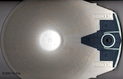
Image: Primary hull bottom after painting.
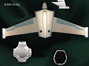
Image: Undersides of the roll bar, etc. Image: Warp nacelles. Image: Aft bulkhead.
|
I looked long and hard at Don's fantastic work before I started this project; Don Matthys is a master when it comes to lighting and painting. His ship can be seen at www.culttvman.com and you definitely want to take a look at this beautiful ship before you start. I knew ahead of time that there was no way that I was going to be able to duplicate it, but I also realized that there are scale modelers out there like myself that want to try as best we can to approach that level of craftsmanship. So my goal when I started the project was to build a ship that included a nice lighting and painting scheme, and also one that was both realistic and affordable. While I do not have anything against going out and buying expensive lighting material and air brush equipment, I do think that one of the greatest joys of scale modeling is to take a kit and try to do something with it that challenges you to think of new methods and ways to create a ship that is personal and fits your own style of scale modeling. It's easy to take a kit out of the box and paint it and glue it together according to the instructions. The fun part for me though is doing the research, looking at the videos, and the material that's on the web pages to find ideas and accurate material. I believe that when I first viewed the movie "Star Trek II...The Wrath of Khan" and saw Reliant for the first time, I felt what a lot of scale modelers felt: the desire to build the thing. It would be a while before we modelers could get our hands on the kit though and by the time I finally got around to building her, several years had passed since the movie came out. But it was well worth the wait to me as I practiced and honed my skills. So put on your thinking caps and follow along as I explain how I built "Reliant on a Budget". Research Your ProjectThe very first thing I would recommend after you buy you kit is to watch the video (or the DVD now that it's out) and freeze frame it to look at the ship and look for the little details you might want to incorporate. Also check out the pictures of the studio model at Pedro's Shiporama and the excellent lighting of Don Matthys at CultTVMan.com. Both are among the best references on the Internet for Reliant detailing. Examine Your KitNow that you have a general idea of what you want to have your ship look like, take the kit out and see what's in the box. When I first opened mine one of the first things I noticed was that there was a wealth of extra clear styrene. This would prove a good source of material described later. You will want to use a good Exacto knife with a #11 blade to cut the parts free and then sand off any extra plastic still remaining. Be sure to save all the spare styrene that you removed your parts from for later use. Choosing Your Light SchemeOne of the early decisions you are going to have to make is how you want to light your ship. In keeping with building my version of Reliant as inexpensively as possible I chose to use ordinary flash light bulbs. I used a total of eight (yes, eight) "D" cell batteries to provide enough power to illuminate the whole ship. It will greatly help things if you make a small diagram of the ship and decide where you want to place your bulbs now so that you will have it handy when you start wiring later. Start Painting Your ShipHaving chosen your light scheme, you will want to start doing some of the base coat painting. I don't have an airbrush and probably will not invest in one because of the trouble it takes to set up an area to use one safely. So I chose to use various spray paints. For the outside of the ship I chose to use flat white. It doesn't matter what brand you use as long as it doesn't say on the can that it is not recommended for use with plastics. So buy what's on sale at Home Depot or wherever you like to buy your paints and start with painting the outsides of all the parts (except for the clear pieces). Use a couple of light coats and allow it time to dry between coats. Don't try to paint it all in one coat or you'll end up hiding some of the fine detail on the individual parts. After it's dry, you need to mask off the outsides and paint the insides of all of the parts with a dark color (I recommend olive drab or flat black) so that when the ship is lit there won't be a lot of light "bleeding" through the hull and nacelles. |
|
The Aztec Pattern Nightmare
Okay, by now if you've looked at enough pictures of the studio model and some of the other ships you will have noticed that there is a subtle pattern on the ship. It's known as the "Aztec Pattern" and if you try to go at it one tiny bit at a time your going to spend the next six months painting tiny little squares and "figures". The easiest way I found to overcome the Aztec challenge was to use ordinary frisket paper that you can buy at most art supply stores to create a template that would be both reusable and durable. I recommend using "heavy" tack rather than "medium" tack. There is a fine resource for creating your own templates at Jon Glentoran's "Beyond Antares" web site. For my own ship, rather than going out and purchasing a lot of different paints and trying to mix them in order to get the right shade, I chose again to visit my favorite paint store (with the top of the already painted primary hull) and buy a single color of paint that was just BARELY a shade darker than the paint that I used for the outside of the ship. In the photos it looks a lot darker than it really looks in person because I used a bit too much flash in taking the photos of the ship, but I never said that I was a good photographer. When you prepare your templates, what you want to do is to put your copy of the Aztec pattern on top of several sheets of the frisket paper and use a NEW blade on your Exacto knife and cut out the pattern on a butcher block. The wood of the butcher block will allow the blade to cut through three or four sheets of the frisket paper at a time without damaging the blade (or your coffee table if you happen to be watching TV at the same time). For the aft sections of the upper and lower sections of the primary hull I had to freelance a bit. There are no patterns available for this section (unless you want to shell out money for brass templates) and I found that it was easy to cut a few pieces of frisket paper free hand with the patterns. No, this isn't exactly like the studio model, but in what few photos I could find of the thing there wasn't enough resolution to make out the exact pattern. Besides, this is going to be YOUR ship and you get to decide how much or little of the Aztec pattern you want to use for these areas. "Beyond Antares" web site has the information for painting the pattern on the U.S.S. Enterprise, and the nacelles and most of the primary hull are the same on Reliant and you can use it as a good reference. Take your time with the Aztec Pattern. It took me about two weeks to cut out the templates and paint to my satisfaction. Since I was using ordinary spray paint I chose to paint two sections of the hull at a time (using a single light coat and masking off the unpainted sections) allowing the paint to dry for only about five minutes before pulling the frisket paper template off of the part of the ship that I was painting. Wait too long and the frisket paper dries with the paint on the hull. Pull it off too early and you'll smear the paint. I recommend practicing on a sheet of aluminum foil a couple of times to get the feel for how long you need to wait and how much paint to apply. Painting the DetailsThere are of course a lot of areas that using a can of spray paint just won't cut it and you're going to have to start making some decisions about how you want to approach doing some of the fine detail painting. For this I have learned to appreciate the joy of felt tip markers, toothpicks, and a fine tipped paint brushes. I'll break down the fine painting into the individual sections that I worked on. For the Main Bridge dome I used a Testors paint pen. These are fairly inexpensive and more than pay for themselves when it comes time to get into some of the really tight places and sharp corners. I used silver on the dome and then used a fine paint brush to paint a single light coat of white. The result is a grayish looking silver that looks like it does in the movie. Use the same method for the sensor dome on the lower section of the primary hull. There is an area just below the ridge where you need to use Duck Egg Blue (Model Master FS35622) to paint all the way around. Simply mask with masking tape and use a fine tip paint brush. Mine required two coats to make it dark enough to show up since duck egg is a fairly light color. When you do you research you'll notice there are some versions Reliant that show a thin red line on either side of this duck egg blue area. After viewing the tape and looking closely I could find no evidence of this on the actual studio model and opted not to include this on my version of Reliant. However, it does look pretty nice on the ships that I saw that included it and you may wish to add this red striping to your own ship. For the clear impulse engine domes (both dorsal and ventral) I chose to use finger nail polish remover (50 cents for those keeping track of the budget so far). Nail polish remover has diluted acetone and I used a paper towel to wipe the insides only with the solution in order to give the domes a translucent effect. I didn't want the parts to be totally clear or the lighting coming through would be too bright. I went back to the Testors silver paint pen to carefully paint the raised portions of the domes. If you accidentally paint off of the raised grill of the domes don't worry about it. Just let it fry and GENTLY scrape it off with the edge of a sharp blade. The warp engine nacelles were next on my agenda. In the photographs and in the video of the ship you can see an area just forward of the warp nacelle grills that has a slight red color. This is one area where I chose to depart from the true color scheme. You may wish to include this area of red painting detail on your ship. For the engine grills I started by painting the whole grill with Model Master intermediate blue (FS35164). After allowing this to dry thoroughly I used a black magic maker to carefully color the raised portions of the grill. Use this same method to paint the warp drive intercoolers (parts #22). Paint the areas on the rear "fins" and forward parts of the engine according to the directions that came with the kit with duck egg blue. Again, I used two coats on these areas to bring out the color a little better. On the "fins" there are two dots of white paint on the dorsal and outer edge to simulate lights. I used a toothpick to get a single SMALL drop of paint and just touched it to these areas and allowed it to dry. Finally, paint the two small domes on the upper sections of the nacelles using flat red and a fine tip paint brush. The long range sensor array (sometimes humorously referred to as the "roll bar") is painted according to the directions in the kit. I looked at the video and the studio model and couldn't find anything that was not depicted in the painting instructions. I have seen some photos of completed kits in which the forward and aft photon torpedo launchers were painted red on the interior portions of the parts (#5 and #6). Again, going to the video I did not see this and chose to use Light Ghost Gray (Model Master FS36375). One area not mentioned in the painting instructions is the two pair of short red stripes of paint located between the fore and aft phaser arrays. You can use either a red fine tip marker for these or a fine tip paint brush and red paint. I tried both and ended up using the paint because it was more aesthetically pleasing to the eye. There are a few miscellaneous areas that you may want to take care not to overlook. Aft of the bridge area there are five small indented squares that the painting instructions call for duck egg blue. This is not correct. You need to use intermediate blue for this area. On the edges of the aft hull bulkhead (Part #10) there are ridges that need to be colored black. I used a fine tip black magic marker to "paint" these areas and allowed the ink a couple of days to dry before handling the part again. After allowing the ink to dry paint the inside and outside of the shuttle bays with Tamiya Blue (Color #X-23) and the impulse engines Tamiya Red (Color #X-23). On the upper and lower sections of the main hull are three sets of phaser arrays. Paint the square area around the raised phasers yellow and the phasers themselves red. After painting these you may want to mask them off with tape until you have completed assembly of the the main hull. Or you may choose to wait until after assembly to paint them. Either way works, but had I to do it over again I would have chosen to paint them after assembly to save myself the trouble of masking them. Along the upper and lower edges of the forward section of the main hull are two more areas of yellow with two short horizontal strips of red. Definitely paint these areas after assembling the hull. I painted them prior to final assembly and had to go back and retouch them! Starting Subassembly and LightingThere are four sections to Reliant that need to be assembled as subassemblies...the nacelles, pylons, aft bulhead and the lower saucer section. For each of the subassemblies make sure that you give yourself plenty of time to allow any glue and putty to dry. Remember to glue, dry, then putty and dry before you remove any excess adhesive material. This will make sanding the edges of parts easier. We will also begin to do some budget lighting in the following subassemblies so make sure that you TEST and TEST again the lights before you glue. Do NOT apply full voltage to the lights or you'll burn them out. One "D" battery will be sufficient to test each light. Starting with the simplest, you want to want to assemble the aft bulkhead which contains the blue shuttle bays and red impulse engines. You'll need to make sure that you've already painted the inside of the bulkhead black before doing this. I chose to sand the rear of the docking port lights (parts #105) in order to diffuse the light coming from inside the ship a bit. After this has dried attach the rear bulkhead to the lower part of the saucer section. Use white model putty to seal the edges. Set aside to dry. The main sensor array (roll bar) can now be assembled. This is step number five on the instruction sheet. Follow it and make sure that you use putty around the edges and sand and smooth them out after it's had time to dry. If you have chosen to use running lights on your nacelles then this is the time to pull out you diagram and decide how you want to place your bulbs. This is also where we start getting back to the budget theme of this article. Remember all of those little clear Christmas light bulbs that you have laying in storage? Well pull them out because we are going to start making some use of them here. For my running lights I chose to indirectly light them using penlight flashlight bulbs. To do this I CAREFULLY broke off the very tips of the Christmas light bulbs. This will leave you with a small tip of glass with just a small amount of the bulb where it begins to flare away from the tip. Put the two halves of the nacelles together and secure them tightly with rubber bands. Mark and drill out a hole in the rear of the nacelles for the tips of the Christmas light bulb so that only the tips will extend out from the hole. Remove the rubber bands and open the nacelles back up for the next part. The remaining portion of the bulb (the flared part) should be able to fit inside the nacelle. If it not, repeat the process. You only want a the tip of the bulb to extend outward about a couple of millimeters. Now use a piece of the spare plastic styrene mentioned earlier to make a mount for the flashlight bulb on one half of the nacelle and extend the wires forward to the opening at the top of the nacelle where the pylons will attach to the nacelle. When attaching the wire to the bulb you can either purchase lamp bases or you can solder the wire directly to the bulbs. Wiring directly to the bulbs will save some money, but you will have to be very careful that you don't allow the current to cross and short the circuit to your light bulb. Allow the bulb to rest in the middle of the space inside the nacelle and give yourself about eight inches of extra wire so that you can extend the wire through the pylons and inside the lower saucer section. Now before we get to the final assembling of the nacelles let me share with you the joy of Pop Tarts. Right now you're saying "What the heck is he talking about Pop Tarts for?" Well not only are they tasty, but they come individually wrapped in MYLAR! [For our non-American readers, Pop Tarts are pastries one puts in a toaster to heat before eating. This same thin silver foil can be obtained from candy bar wrappers and the like - Ed.] So eat the Pop Tarts and use the mylar to coat the ends of the nacelles. Just use a thin layer of glue and apply the sheets of mylar inside and then trim off the excess. It will reflect a lot of light from the bulb up through the Christmas light tips that will be extending through the top of the rear of the nacelles. It makes for some very nice looking running lights. Now you can go ahead and glue and putty the nacelles together. Make sure to extend the wiring for the lights out the top of the nacelles. Set the nacelles aside to dry and go jogging to pay for your Pop Tarts. Now that you have the nacelles assembled, you need to assemble the pylons that will attach them to the saucer section. Using the inward half of each pylon attach them to the lower section of the saucer and mark where the wiring for the running lights will extend inside the ship. Drill a hole large enough to LOOSELY accommodate the thickness of the wire through both the inner half of the pylon and the lower saucer section. Be very certain of where your marks are for where the wires will go into the saucer section. Use a sharp knife to carefully score a tunnel on the inside of both halves of the pylons to receive the running light wires. Assemble the pylons as seen in part 2 of the instruction sheet while using the tunnels you've created to run the wires up through the pylons and out the inner half of the pylon where you have drilled your hole. The extra wiring will extend inside the ship later. Let dry and eat some more Pop Tarts. You'll need the mylar in the next section.. Starting Subassembly and LightingThe lower saucer is where you are going to be placing the all but one of the flash light bulbs to light your ship. There are some intrepid souls out there that put lights in the sensor array, but I decided not to go that route. At this point you will want to start drilling all of those tiny little holes on the sides of the lower saucer section, the larger holes on the upper and lower section of the saucer section, and the windows that are on the "face" of the upper portion of the saucer. I used a tiny drill bit that I purchased at the hardware store to drill the small holes and a slightly larger bit for the larger holes. You can tell which holes are to be small or large simply by looking at the drilling site and also by viewing the video tape of the movie. The windows on the face of the upper saucer section will require you to drill small holes in the middle of each window and then use your Exacto knife to cut away until you have a nice square window. This will probably take a couple of days to do if you're taking your time as I was. For those still keeping track of the budget theme, the drill bits were about 49 cents each. Buy a couple of each in case you break one since they are pretty delicate. At this point I decided to use the small tabs that are attached to the base that comes with the ship. They are extra pieces of clear plastic and since I decided to use a different way to display my ship the base itself even became a usable source for light mounts. Back to the smaller tabs though. I chose to drill the upper and lower sections of the hull where there would be running lights. These are located as 9:00, 12:00, and 3:00 (looking forward and overhead from the aft of the ship) on the saucer. Sand down the tabs (you may wish to use the tips of the Christmas light bulbs also if you chose) until they fit smoothly into the holes you drilled for the running lights. The running lights on the bow of Reliant should be left clear. There are also two pairs of running lights on the top and bottom of the aft bulkhead area that should be clear. Paint the running lights on the port side of the ship Tamiya #X-27 clear red and those on the starboard side with Tamiya #X-25 clear green. Glue them all into place after allowing the paint to dry. Ok, at this point we're going to have to spend some money unless you just happen to have a bunch of old flashlights [torches] laying around. I went to Radio Shack and bought 2 bulbs that you would use for a 4 "D" cell flashlight and 2 of the screw in type bulb mounts. I also bought eight more of the penlight sized bulbs and the 8 more of the bulb mounts for them. I used a bunch of the wires that I had in an old telephone cable to serve as wiring to the mounts. I think that I spent about $20 for the bulbs and mounts. Assemble each light bulb with it's base and solder with about ten inches of wire. This is excessive, but wire is cheap and you'll trim the rest later. AGAIN, test each bulb using only one "D" cell battery to make sure. Before placing the bulbs I again used my trusty Mylar that I had from the Pop Tarts and glued it all over the inside of the upper and lower sections of the saucer section...anywhere that I could place mylar without covering windows and port holes. For the windows I chose to use a piece of transparency paper [acetate] that you would use for any copy machine. It's thick and sturdy enough to use for the windows and slightly opaque so you won't have to sand it down. Carefully measure out small sections of the transparency paper and glue it on the inside of your windows and port holes. Be careful not to place any glue where it might run over into a window. You want to use small drops of glue at strategic points and not use a lot of glue and just stick it on the inside. You'll just end up with a bunch of your windows with glue sticking out like a sore thumb. Back now to the lighting. You now have your windows in place and the nicely reflective mylar spread out inside both halves of the saucer section. It's time to do a little lighting. Start with the upper half of the saucer section. In the center of the area where the bridge dome is going to be placed in the final assembly drill a LARGE hole. It needs to be ALMOST the diameter of the whole bridge (Part #25). This will allow a lot of light from the bulb to pass up and into the bridge area. AFT of the hole you will need mount one of the two larger flashlight bulbs. I chose to use a piece of the base that comes with the ship to mount this bulb. For this (and all subsequent light placements) you need to remove a small amount of the mylar so that you can glue plastic onto plastic. Glue the bulb mount using polystyrene glue or rubber cement onto the base. As an extra measure to make certain that the bulbs did not shift their position I tied the mount onto the base with several wraps of thread. You need to now repeat this same procedure on the lower half of the saucer section with the second of your larger bulbs. This is the main source of light for the Space Planetary Dome (Parts #19 and 104) area under the ship. For the remaining lights, mount them so that they are not in contact with the plastic on the lower saucer section at the points where they can cast as much light as possible outward from the inside of the Saucer section. You will notice that penlight bulbs are made to spread light in an area that covers about 180 degrees (my estimate). The placements I chose allow light to shine to the edges of the saucer section (which illuminates the running lights), to the impulse engine domes (both top and bottom), and lastly aft towards the impulse engines, docking lights, aft running lights and the shuttle bay areas. At this time you want to again start testing your bulbs to make sure that they are secure in their individual bulb holders and also to make sure that you have the correct alignment of positive to negative. You're still testing one bulb at a time here, so keep using the single "D" cell as your power source. Also make sure that you have your bulbs oriented inside the saucer section to get as much light shining out as possible. At this time I chose to start connecting individual bulb wires together by twisting the wires together and cutting off any extra wire, testing each as I went along. You're going to need a lot of space now because this is the point where you want to bring the wiring from the nacelle lights inside the lower saucer section and the ship is going to have to lay on a flat surface looking like some clam or frog you dissected in high school with wires looking a bit like spaghetti. When you're finished twisting all of the positive pole wires and negative pole wires together use a bit of solder to secure the wires. Keep testing your "circuit" as you go along to make sure you haven't crossed poles or have any loose bulbs. This is also a good time to place the two halves of the saucer section together to make sure you have plenty of clearance for the bulbs and also to check for any "leaks" where you might have light shining through in places where you don't intend for it to. Assembling the Saucer SectionBefore you begin this step, first take several tin sheets of styrene if you have it and glue them together so that you have about a inch square piece of styrene that is about 15 mm thick. Set it aside and allow it to dry overnight. A hard piece of wood will do just as well with the same dimensions. To mount Reliant I chose to use a piece of brass rod that was about eight inches long. In order to accommodate the brass mounting rod carefully drill a hole in the lower saucer section exactly 55 millimeters from the center of the lower impulse drive dome that is slightly smaller than the diameter of the rod. Remember the old adage to measure twice and cut once. Use a sharp blade to slowly expand the hole until it receives the rod (anyone having carnal thoughts at this point is excused) smoothly. Place your rod though the hole and place the two halves of the saucer section together. Use the rod to score and mark the surface on the inside of the upper saucer section. This is the point where you need to drill from the inside out another hole slightly smaller than the diameter of the rod. Again, expand the hole, but so large that the rod can go through the upper saucer section of the ship. Yes, I know that this is going to make a ugly hole, but we're going to come back to that in a little while. Use a piece of wire (some of that extra Christmas light wire works REALLY well here) about a foot long and solder it to the two ends of the light wiring that you soldered together in the last step. Drill a hole on one side of the brass rod about one inch from the ends and run the wire through the holes and out of the ship. You'll have extra wire that you can trim off later. Drill a similar diameter hole that DOES NOT go completely through the block of styrene (or wood) you assembled. This part is going to receive the upper end of your mounting rod. Next use SUPERGLUE the block of styrene (or wood) directly on top of the hole inside of the hole you created in the upper saucer section and allow this to dry. You definitely will want to make sure that the mounting rod lines up with the hole in your styrene block so that the ship rests on an even keel. It's a bit wobbly right now, but we're going to correct that later...r.r.r.. Time for one last check of your lights. By now you should be able to use all eight of your "D" cell batteries. Check everything thoroughly because this is the last chance you'll have before gluing the upper and lower sections of the saucer section together. Are the bulbs snug in their holders? Are the bulbs oriented to shine as much light as possible out of the windows and aft bulkhead? Does the mounting rod align with the styrene (or wood) block on the inside of the upper saucer and is the ship sitting evenly on the mounting rod? Are there any places where you have light leaking out that you won't be able to reach once the saucer section is glued together? If you're satisfied with everything, then now is the time to glue your upper and lower halves of the saucer section together. But before you start make sure that you have polystyrene glue, putty, some clean clothes pins, and some CLEAN rubber bands. I used all of these to assemble the saucer section. You may need some C clamps for the aft area of the top saucer section where it meets the aft bulkhead. My Reliant needed to be clamped firmly to align properly. Once I had everything in place that I needed I worked rather quickly. Time to put the saucer section together. First put couple of drops of glue in the hole of your styrene mounting block and insert the upper end of the rod into the block. Then put a bead of glue at strategic points around the edges of the lower hull and on top of that place a bead of putty completely around the edges of the upper saucer section. Line up the upper and lower sections of the saucer section and seal them together using the clothes pins, rubber bands, and in my case the C clamps on the aft section. The nacelles at this point are going to dangle so be careful with them and don't pull on them. There is going to be some excess glue and putty, don't worry about it because you're going to so be able to sand it away later. Lastly, GENTLY push the mounting rod upwards to make sure that it is flush with your mounting block. At this point I stopped and just let the whole thing dry for about three days until everything was completely dry. After I was satisfied that everything was dry I went back and sanded off any excess glue/putty with some fine grit sandpaper. Remember that big hole in the top of the saucer section? When you glued the styrene block to the upper half of the saucer section you created a place to strengthen your mounting rod. Use a small drill bit at this point and drill a small hole inside the bigger hole in the top of the saucer. Place a drop of superglue into the smaller hole and place a screw into the styrene mounting block. Fill the larger hole with putty and allow it to dry. Sand excess putty away and paint over the spot where your hole was with the same color you used to spray paint your overall ship color. That's how I mounted my model and I've found that this creates a VERY strong mount and its more attractive (at least to me) than the base that came with the ship. Attaching the Pylons and NacellesThe most important thing that you want take into account when you attach your warp engine nacelles and pylons is how they are going to be oriented. You want to make sure that the nacelles are level, evenly spaced between themselves, and not at some odd angle. So make sure that you test fit them before you glue them into place. One gripe I have about this kit is the two little knobs on parts 15 and 16. I know that they are there to help orient the placement of the pylons on the ship, but I found that they just got in the way more than anything else, so I sanded them off. So, test fit the pylon/nacelle subassembly that you put together earlier and get an idea of the orientation. Before you glue, get a water pitcher (taller than your mounting rod) and some books. Tuck your excess wiring into the saucer and glue the pylons to the saucer section. Use rubber bands on the top and bottom of the pylons to hold them in place vertically. To horizontally align the nacelles, place the ship (we can call her a ship now) on top of the water pitcher with it's mounting rod inside the pitcher. Now use stacks of books (or whatever you have that's stable and handy) to raise or lower the nacelles into their proper alignment. Once you're satisfied that everything is STABLE and isn't going to shift, walk away from it and let it dry for a couple of days. Fill in the seams with putty and sand it smooth after it's dry. At this point go ahead and attach the Sensor Array subassembly and allow it to dry. Once again, putty and sand the seams until smooth. > Assembling the Bridge Section Before you assemble the bridge section, you might want to take a look at some of the photographs available on the Internet. In some of them you'll note that on either side of the docking port there are a couple of small crescent shaped areas that you may wish to have light shining through. To do this I used an Exacto knife to slowly cut out these two areas. Then I placed a piece of clear tape on the back of the docking port (Part #27) and used polystyrene glue and filled them in. After allowing them to dry I removed the tape and used a to apply a small amount of nail polish remover to opaque them. Glue and putty this part to the main bridge (Part #25). Paint the inside of the assembly black. There is a small running light located just aft of the bridge dome. Use the same method used with the Christmas light bulb and place a clear bulb tip in this position. Glue more of the Mylar to the interior, but be sure to trim away any of the Mylar that will keep light from the bulb you placed in the upper saucer section from shining through the docking port, running light, and the slits on the underside of the main bridge assembly. Test fit the bridge assembly onto the top of the saucer section to check for light leaks and correct as needed. Once you're satisfied that there are no lighting leaks go ahead and glue and putty your bridge to the saucer section. Sand away any excess putty and touch up the paint where the excess putty was. You should have a nice smooth transition from bridge to saucer. Assembling the Space Planetary DomeThe Space Planetary Dome is fairly straight forward. Paint black and attach Mylar to the interior of Part #19. Paint the interior (do not glue on any Mylar) the interior of clear part #104. Allow to dry and then glue the two pieces together. After allowing this to dry over night, use a drill to tunnel two parallel tunnels that extend from the edges of Part #104 in towards the center of the Dome Assembly. They should extend inward about half an inch. Take your time and test the amount of light you're getting to shine through these tunnels until you're satisfied with the result. As with the bridge assembly, glue and putty the Space Planetary Dome to the Saucer section and allow to dry. Again, sand away the excess putty and touch up the paint to that you have a smooth seam. Finally the Final AssemblyBy now you're just about finished. For displaying my version of Reliant I chose to use a wooden box painted the same color white as the hull. I chose to use two battery holders available at Radio Shack to contain my eight "D" cell batteries and my toggle switch. The cost of these parts was about $5 for those still keeping track of "Reliant on a Budget". To receive the mounting rod I drilled through the top and then partially into the bottom to secure the rod. The holes should fit snuggly around the rod. Don't glue the rod in place so that you can replace the batteries at some point in the future. Reliant should now be firmly mounted, level and stable. At this point simply connect and solder your wires that come out from the bottom hole you drilled earlier in the mounting rod to the toggle switch. The battery holders come with red and black wire leads that you connect to the other poles on the toggle switch. MAKE SURE that you have positive wires connected to positive wires and vice versa. Test the circuit as you go along and make sure that you aren't shorting your circuit. Final ThoughtsAt this point make sure that you've done all the touch up painting that you wish to do and apply your decals according to the instruction sheet. So there it is. The total cost of the kit, paints, and lights ran me a little under $50. The actual cost to you may be more or less depending on the supplies you already have on hand since a lot of scale modelers have glues and paints and various pieces of equipment that other modelers might not have in their inventory. There are going to be people who will always write and point out inaccuracies or different ways to approach building this kit. To those people I say that I welcome your comments and suggestions because I'll be starting other projects and your ideas may give me new insight and help me become better at this hobby. It's been a lot of fun (and at times frustrating) as I tried various ways to solve problems that came up during the assembly of Reliant. I hope that this article serves to show some of the ways you can use to build your own version. It's not meant to be the definitive way to build the thing. It's just one person's way of doing it and you'll no doubtedly find innovative techniques yourself that you believe are better. |
![]()
This page copyright © 2000 Starship Modeler™. Last updated on 18 December 2000.
![[Click to enlarge]](tr_reliant_Reltr05.jpg)
![[Saucer top - click to enlarge]](tr_reliant_Fig02.JPG)
![[Bow]](tr_reliant_Fig03_lil.jpg)
![[Roll bar, etc - click to enlarge]](tr_reliant_Fig04.jpg)
![[Rear of bridge]](tr_reliant_Fig08_lil.jpg)
![[Click to enlarge]](tr_reliant_reltr01.jpg)
![[Click to enlarge]](tr_reliant_reltr03_lil.jpg)
![[Click to enlarge]](tr_reliant_Reltr04.jpg)