
|
By Scott Scariot - images & text © 2012 There are times that I think I enjoy torturing myself when I begin a project. This should have been a very straightforward conversion of the AMT Reliant kit. Instead of going that route, I decided I would add a full shuttle bay and light the inside of the model! I did not realize when made this simple decision that this build would become so complicated. |
![[Please click to enlarge]](ss_endo/ss_endo_0607.jpg) |
|
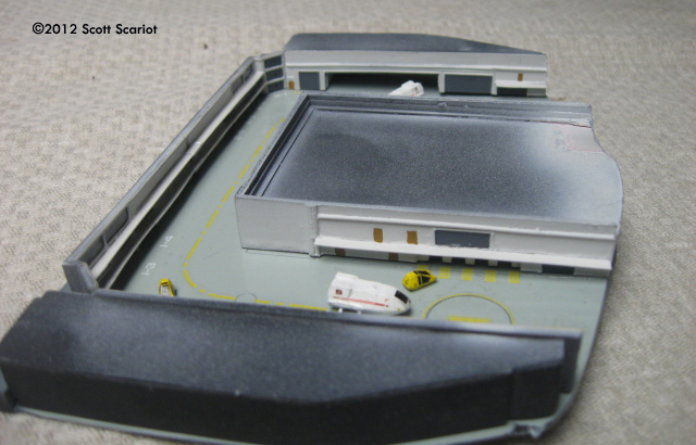
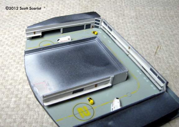
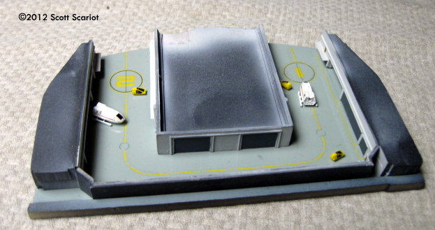
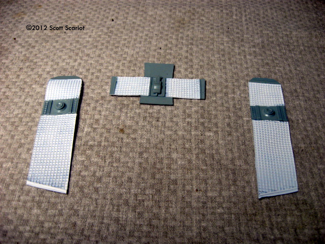
^ Completed shuttlebay. Image: Left side Image: Right side Image: Rear Image: Raising the roof with the side extension pieces. Image: Shuttlebay ceiling parts. Image: Wiring up the shuttlebay.
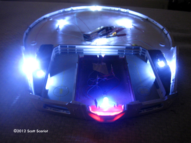
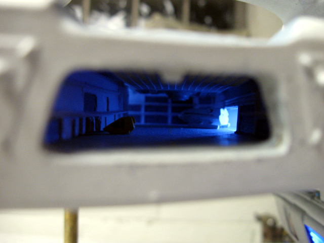
^ Light test Image: Looking good.
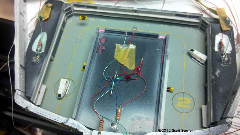
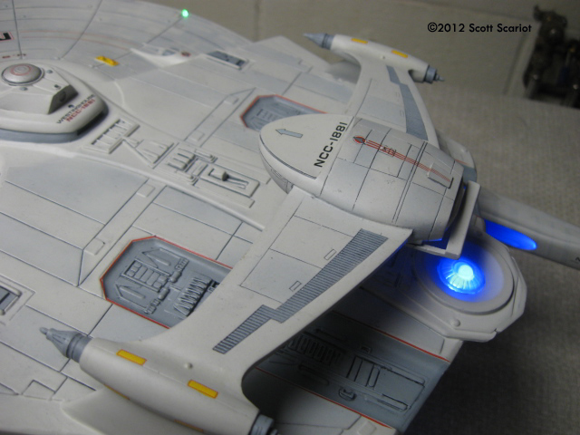
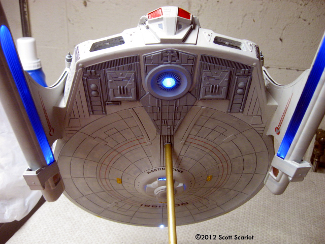
^ All wiring & electronics in place. Image: Impulse crystal lighting. Image: Warp nacelle lighting test. Image: Yup - that looks good too.
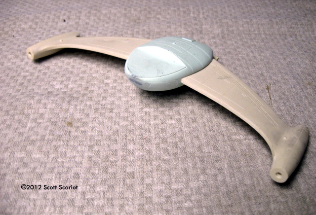
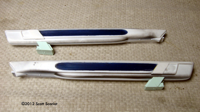
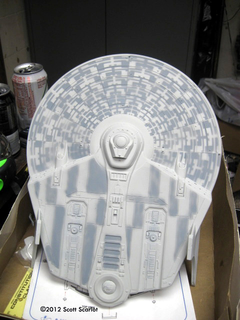
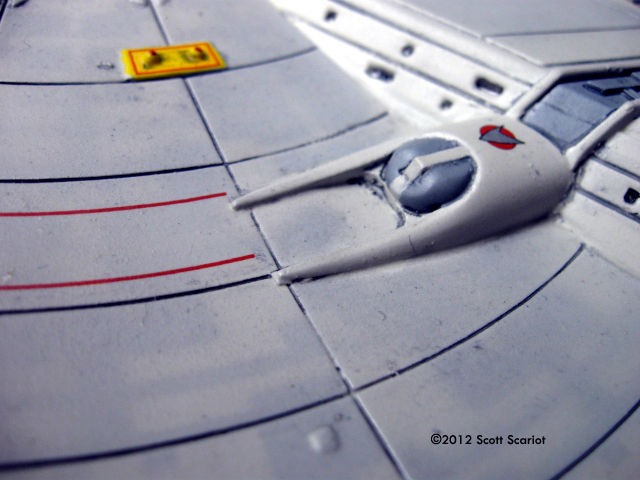
^ Upper saucer mods Image: Sensors. Image: Rollbar & megaphaser mounts. Image: Pylons, with channels for nacelle wiring. Image: Warp nacelle sensors.
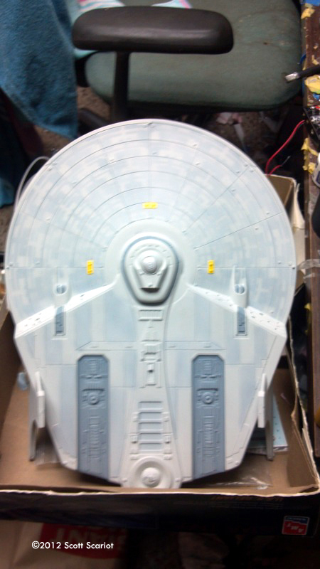
Image: To the paint booth! Image: Basic aztec pattern applied (top) ... Image: ... and bottom Image: Toning it down Image: ... and underneath. Image: Nacelles. Image: Rollbar. Image: Decals - upper saucer. Image: Lower saucer. Image: Rollbar.
^ Done! Image: Detail, lower right. Image: Left side detail.
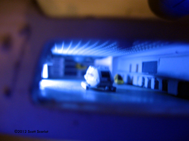
^ From behind. Image: Starboard shuttlebay. Image: ... with lights. Image: Port side. Image: Shuttle.
Image: Starboard side details. Image: Copper nacelle detailing. Image: Sensors Image: Impulse crystal/engines, above. Image: Below
Image: Lights reflecting on the dedication plaque. Image: Lighting in action (mp4 movie).
|
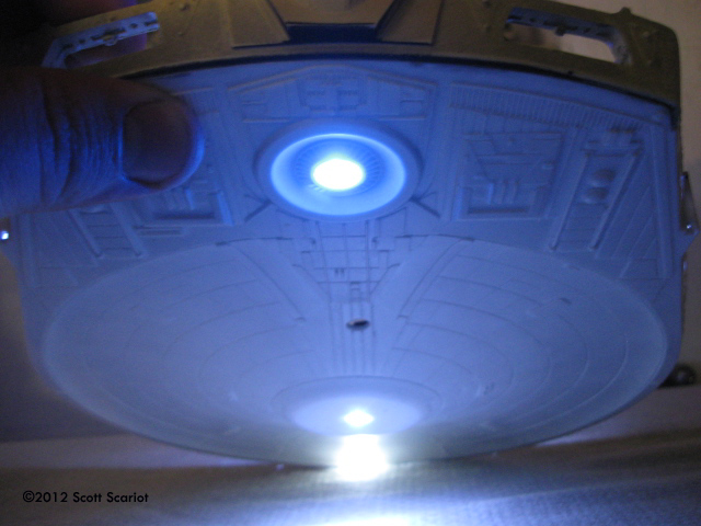
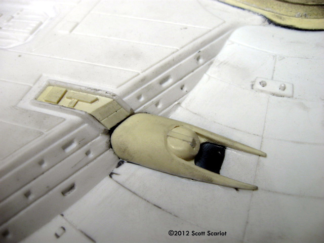
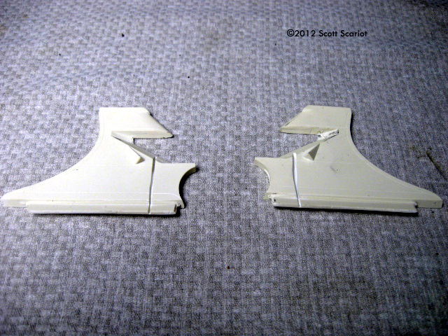
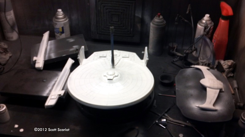
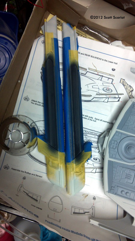
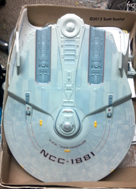
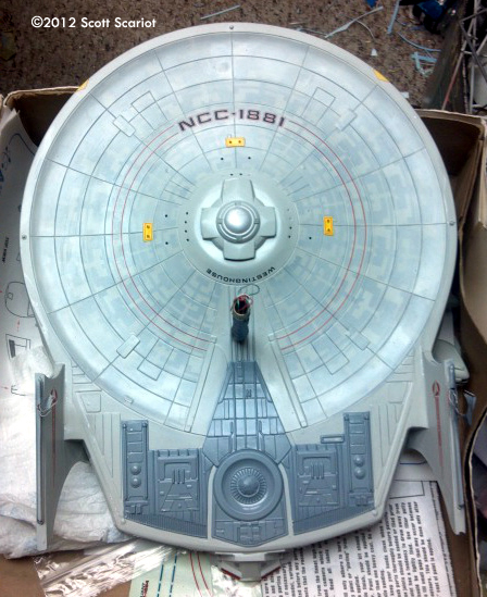
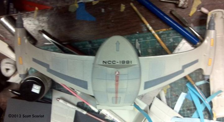
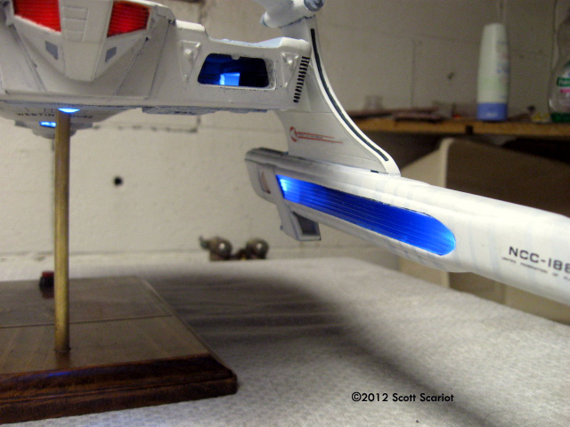
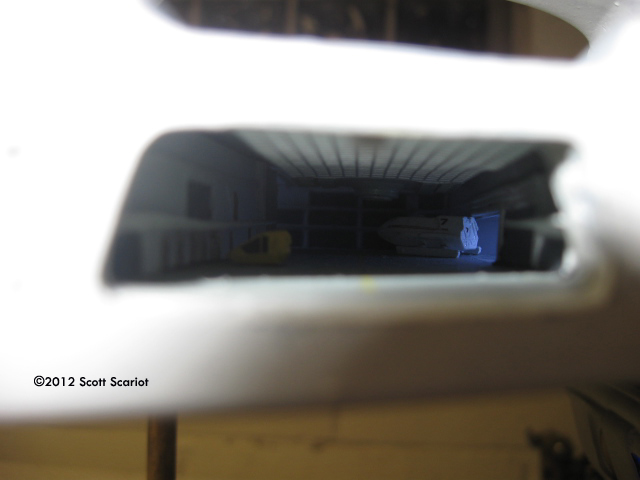
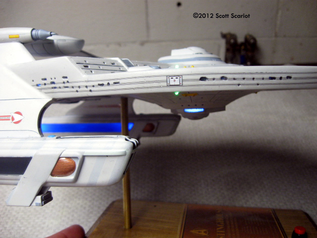
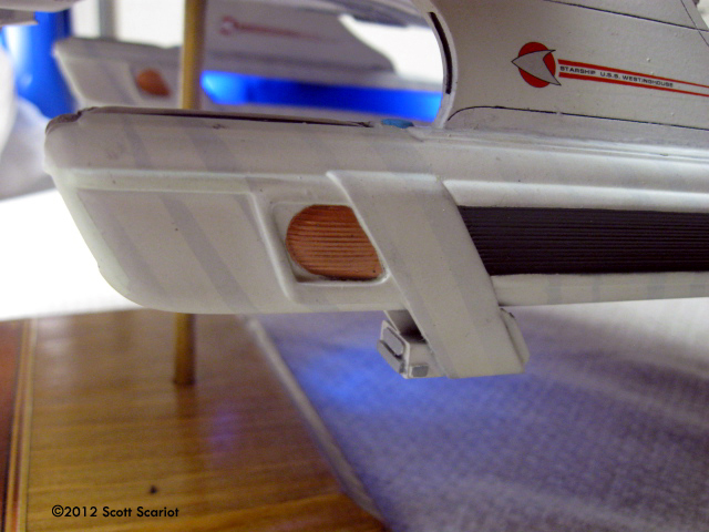
The project started simply enough. The styrene, and resin parts were washed in warm soapy water and were left to dry. The insides of the model were sprayed black as a light block and then white as a light reflector. Shuttlebay The first major assembly was the shuttlebay. I used Federation Models Miranda class shuttlebay kit, which consists of 15 parts. Seven of those parts are the Miranda class Saucer width correction kit. (for those that don't know the original AMT kit was too thin) The remaining 8 parts make up the shuttlebay, 5 for the structure and 3 detail parts for the ceiling. The parts were well cast and fit together nicely. My only issue with the kit is it does not include any shuttles! Federation does sell shuttles and travel pods and work bees in this scale. Why not include one or two with the kit? The shuttlebay parts were all sprayed with primer and then painted. The directions that came with the kit suggested Aircraft Gray for the floor, so that's what I used. For the back wall and "garages" the direction said use the hull color. I decided to use Light Gray since that is my default Federation hull color. Once the garages were painted I did a little detail painting. All of the large shuttle/cargo doors were painted Gunship Gray. The man doors were painted a brown. I also added catwalks made from thin sheet styrene. Since I was lighting the model I also drilled holes in the side garages for LEDs to help illuminate the bay. I wanted shuttles in my shuttlebay, so I bought a set of two shuttles and a set of three work bees from Federation Models. The shuttles cost $10 and the work bee's $6. Since the parts were so small I placed the parts on a piece of tape to hold them in place during priming and painting. I painted the shuttles white. I base-coated the Work Bees with white also. Then I painted the Work Bees yellow. After painting the Shuttles, Bees and the floor of the shuttlebay were coated with Future. Due to the size of the shuttles most of the details were decals. The decals went on okay despite their small size. I then painted the shuttles with a second coat of Future. While that was drying I applied the decals to the floor of the shuttlebay. The decals were VERY thin but went on well. Lighting With the shuttles done and the decals on I could assemble the shuttlebay. Once that was done I had to map out the wiring. My biggest issue was how to light the driver crystal on the bottom of the model. The shuttlebay would cover this area completely. I decided to use a 3mm blue LED. It would be bright and small enough to fit in the area I had to work with. Now I had to get power down to the LED. I drilled a hole in the center of the bay. That allowed me to get wire down to the LED. But, I could also use this as a way to channel wires to any area in the bay I needed and keep them out of site. To light the back of the bay I placed a white LED out of sight right inside the bay. I ran wires down and to the outside for both garages then glued the LEDS into the holes. Before I glued the shuttlebay into the hull I had to attach the parts of the saucer correction kit to the lower hull piece, including the back piece with open shuttlebay doors. With correction kit parts and the wires fed and LEDs working I used JB Quick to glue the shuttlebay into the bottom half of the hull. JB Quick is a fast curing version of JB Weld. It is a two-part epoxy that is very strong and cures in about 5 minutes. The impulse engines were a bit of a challenge for me. They needed to glow red to match just about every Federation starship. The impulse engines are cast into the aft piece of the correction kit. I could cut out the areas, but then I would lose the corrugated detail. Then it dawned on me that I could thin down the resin and if I placed an LED right behind each engine it would glow. So that's what I did. But, because the impulse driver crystal is so close to the engines I had to build a light box to prevent the red light from leaking in. This was actually pretty easy. I cut a small piece of sheet styrene that fit inside the impulse block and covered the LEDs. To light the Driver Crystal I placed a single blue LED at the very back end of the middle shuttlebay garage. I glued the shuttles into the bay with CA glue. Just for a little bit of depth I stretched some clear sprue and drilled little holes in the shuttle bay and a work bee. That way it would appear that it was flying inside the bay. Since the molded in detail on the outside rim of model is incorrect I sanded it off. To replace the incorrect detail I applied window decals from JT Graphics. Then I drilled out the windows. Once they had set I drilled out a few windows in each group. Drilling out windows also meant I had to in some spots drill though the correction kit. For darkened windows I drilled a dimple into the plastic. With the windows drilled out I installed 5 white LEDs inside the hull to light the inside of the model. Since this ship is from the Trek movie era only the inside of the warp nacelles should light up. I cut out the insides of each nacelle. I bought a set of DLM's clear blue nacelle inserts to replace the kit parts. I glued them into place. To light the nacelles I sanded two blue LEDs so they were flat. I glued one LED near each end of the clear part. When powered each led illuminates one side of the nacelle. The effect is good. Getting wires down into the nacelles would be an issue because the pylons were cast as a single piece. The solution for that problem was to cut a channel into each pylon that wire could be fed down into the nacelle. Then the channel was filled in with putty. Flashing Lights In an attempt to make the model stand out a little more I decided to add an effects chip to the model. I bought DLM's Federation Flasher chip. The chip is great because it has two different flash rates. The navigational lights blink slowly and the collision lights strobe more quickly. I bought the complete kit that included everything and once it arrived I assembled the board. The instructions are great so getting the chip together was no problem. After a quick check to make sure everything was working I glued some "legs" to the chip, just some sheet styrene so the chip was elevated inside the model. Then it was glued in place. Then I began wiring the navigation lights I used 3mm LEDs in white, green and red. However they are too big, so I chucked them inside my drill and sanded the tops down. I drilled out the Navigation lights on the model and fitted the LED into each one. I drilled a hole in the bridge for the strobe there. I also had to drill holes into the nacelles for the strobes on the end of each nacelle. So I would know what wires powered the nacelles and what wires powered the strobes I used different color wire to keep the two straight. The bridge module is a resin part. To install the strobe in this part, I cut off the resin navigation strobe. I drilled a hole in the bottom of the bridge module. Then I stretched a piece of clear sprue, cut it down and glued into the hole. Then I glued an LED in behind the stretched sprue. I drilled a hole into the B/C deck and ran wires from the flasher chip to the LED in the bridge module. The bridge was glued onto the B/C deck. I did one final light test and then I glued the two saucer halves together. I clamped the edges and let the glue set. Bringing it All Together The next day I removed the clamps and mixed up some Aves Fixit putty. I filled the seams around the edge of the saucer and I also filled the seams on each nacelle. Once the putty set I sanded the seams. It was time to attach the warp nacelle pylons to the model. This turned into a bigger process than I thought it would. I had to attach and re attach the pylons 4 times! The first time I took the pylons off because the "roll bar" that goes on top of the ship did not fit on top of both pylons. So I pried them off. The second attempt the roll bar was okay but the pylons canted out at the rear. The third attempt the pylons were straight and even but they were canted front to back pointing down. No matter what I tried to do I wasn't able to get the pylon to sit straight. So I began removing resin! I carefully cut resin away from the back of the attachment joint a little at a time until finally I was able to get the pylon to sit straight and true on the model. Now that that was done I mixed up some Aves epoxy putty and filled in the gaps around the pylons. I also ran the wires up the trench I had cut in the pylons and then I puttied over the gap to hide the wires. After the putty cured it was sanded down. Priming & Painting With most of the construction completed it is time to prime the model. Before I sprayed the model I stuffed cotton balls into the open shuttle bay doors to prevent ruining the interior of the bay. I also masked off the warp field grille on each nacelle. The LEDs and the clear bits in the sensor dome were masked with liquid mask. Next I sprayed the model with Duplicolor automotive primer. Once the primer dried I looked at the seams on the model. They needed a lot of work. I did this in stages by first applying a little gap filling CA to the seams, and then I sanded the area down. This process while a bit laborious did take care of the seams on the model. The model was given another coat of primer. Once that had dried the model was sanded with 400 grit sandpaper to smooth it out for painting. The Testors Model Master Light Gray was used as the base coat for the model. Two light coats were applied to the model. Once the basecoat had dried, I was ready to begin painting the aztec pattern. This mottled pattern is on the studio model and there are many ways to recreate the effect. In this scale I like to use paint. I bought a set of photo etch brass painting templates to make painting the aztec pattern easier. This I did in stages too. First, I taped each template down to the model and applied a light coat of Dark Ghost Grey. Then I alternated to the next template and sprayed. It took two days to complete the pattern on the top and bottom of the model. To add a little Aztec to the warp nacelles I wrapped tape along each nacelle and painted the nacelle with Dark Ghost Grey. Once the paint was dry the tape was removed. Now that the base aztec pattern was complete I sprayed over the aztec pattern with a light coat of Light Grey to tone down the overall effect. Now that the aztec pattern was done I had to detail paint the model. Areas on the bottom and top of the model were masked off and painted Dark Ghost Grey. The outer warp field grills were painted Gunmetal, as were the bussard grilles. The bussard collectors were painted with Alclad copper. The RCS thrusters were painted yellow. The bridge and sensor dome got a coat of Alclad Aluminum. I also painted the front of each nacelle Duck Egg Blue. Decals With all of the detail painting done the model was given several coats of Future. After the Future was dry the decals were applied to the model. I got a custom set of decals for the model from JT Graphics. The decal sheet includes everything needed to complete detail the model. Due to the size of the model it took 2 days to apply all of the decals. Once they had set I connected the wires in each nacelle and did a quick lighting test. I found that when I connected one nacelle the strobe lights would not work. I hated to do it but I was forced to crack open the nacelle to find the problem. I was sort of lucky that I was able to get the rear of the nacelle opened up without breaking the entire thing. The issue was the two leads from the LED were touching and shorting out. I pulled them apart and glued the nacelle closed. I re puttied the broken seams and set the nacelle aside. The next day I lightly sanded (to try and minimize damage) the seam and then I masked the rear off and I repainted the seam. After the repair I did a light check and the strobes worked just fine. The nacelles and the sensor pod were glued to the model. The seams were filled with Aves and then smoothed down as much as possible. The next day the seams were painted Light Grey. Then the model was given another coat of Future to protect the decals. The styrene kit has many recessed panel lines, so I used a "sludge" wash on the model to incorporate them into overall look This is a wash made of water and dish soap and some acrylic paint for color. The dish soap helps brake the surface tension of water and helps it flow easier. Since the kit has nice deep panel lines - "trenches" would be a better word - the wash went on easily. After it dried I removed the access wash with a damp rag and cotton swabs. I touched up a few areas with more wash but I was pretty happy with the results. At this point in the build my compressor died so I could not spray "flattened Future" (Future with a flattening agent mixed in to make it semi-gloos instead of super shiny) on the model like I usually would. I bought a rattle can of Testors Flat coat. I applied it to the model in several light coats. Once that had set I removed the masks and gloss coated the lighted parts. Base To display the model I used a wooden plaque. I hollowed the bottom out with a router. The plaque was stained and polyurethane applied as a protectant. I placed 2 AA battery holders in the base. I wired them up in parallel to double the run time. I also drilled a hole for a switch. A brass rod glued on the inside of the model was mounted to the base. I attached a dedication plaque to the base. I connected the wires to the switch and the batteries. When I pressed the switch the lights came on. Conclusion This was an interesting build. I am very happy with the results. The model looks great. The shuttlebay adds a nice touch. The Alliance conversion is a nice kit. The aztec pattern turned out well too. I should have added more white LEDs to the inside of the model, but that is a minor issue. The whole project took 5 months to complete. If you have a spare Reliant kit lying around I would recommend converting it into an Endurance class starship. Please note that the opinions expressed in this article are those of the reviewer. |
![]()
Go back up | Star Trek: Federation | Starship Modeler Home | Site Map | Feedback
This page copyright © 2012 Starship Modeler™. First posted on 23 October 2012.
![[Please click to enlarge]](ss_endo/ss_endo_11.jpg)
![[Please click to enlarge]](ss_endo/ss_endo_01a.jpg)
![[Please click to enlarge]](ss_endo/ss_endo_01.jpg)
![[Please click to enlarge]](ss_endo/ss_endo_17.jpg)
![[Please click to enlarge]](ss_endo/ss_endo_0609.jpg)
![[Please click to enlarge]](ss_endo/ss_endo_28.jpg)
![[Please click to enlarge]](ss_endo/ss_endo_29.jpg)
![[Please click to enlarge]](ss_endo/ss_endo_0608.jpg)
![[Please click to enlarge]](ss_endo/ss_endo_35.jpg)
![[Please click to enlarge]](ss_endo/ss_endo_0610.jpg)