
|
By John Klein - images & text © 2008
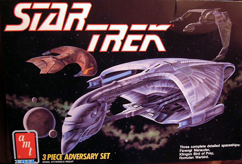
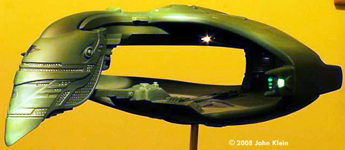
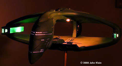
This a look at my build-up of the 1/3200 scale Romulan D'Deridex Class Warbird, part of AMT/Ertl's 3-piece adversary set. General Overview The kit itself is quite simple to construct, being comprised of only a dozen fairly large parts and six clear inserts which can be built into six sub-assemblies. While well detailed, the fit of the parts, especially the upper and lower hull sections is quite sloppy and needs a fair amount of putty and patience to complete. I chose to complicate things a bit and add an internal lighting rig. I built one of these kits a number of years ago without the addition of windows and lighting it just doesn't look right devoid of this prominent design feature. |
![[Please click to enlarge]](jk_ddrex_Display.jpg) |
|
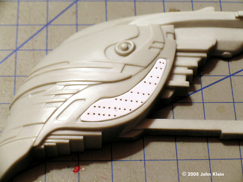
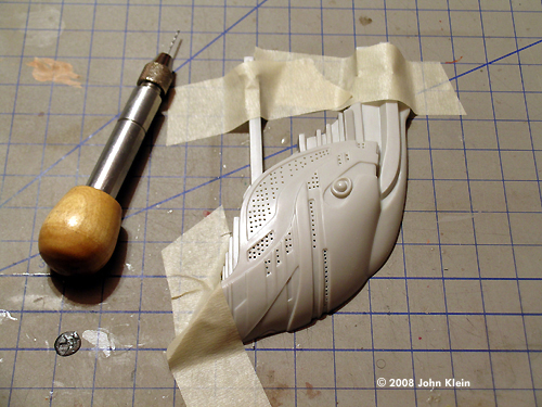
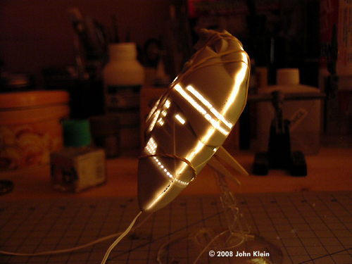
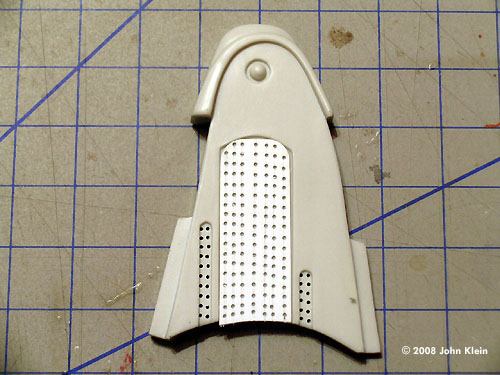
Image: Starting point Image: Bridge halves Image: Interior painted Image: Window template Image: Template in place Image: Windows drilled out Image: Bridge wiring Image: From the front Image: Tail window template, in use Image: Template and results Image: Wiring/light in place Image: Tail light test Image: Nacelle wiring Image: Nacelle tip lit up Image: Light test for the nacelles Image: Lower hull, wired Image: Epoxy putty holds the connector for the stand securely in place Image: Umbilical Image: Joined and puttied Image: Circuit test Image: All the sub-assemblies, test fit Image: Final bench test Image: Front/left view Image: Again, in darkness Image: Port side Image: Another look Image: And another |
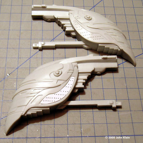
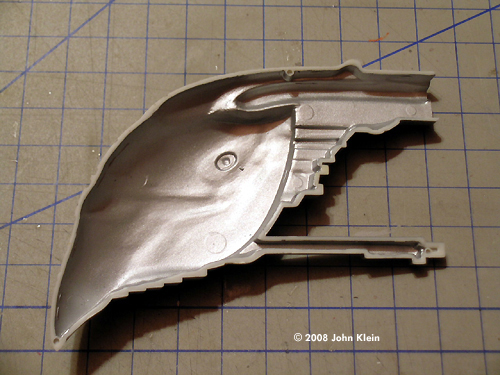
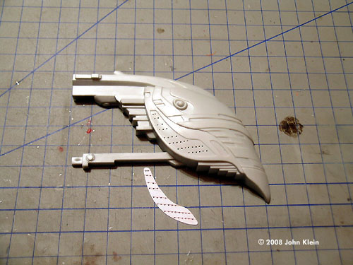
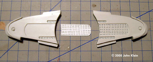
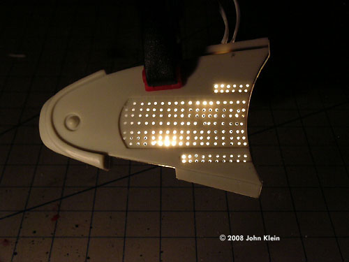
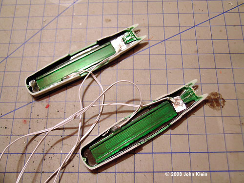
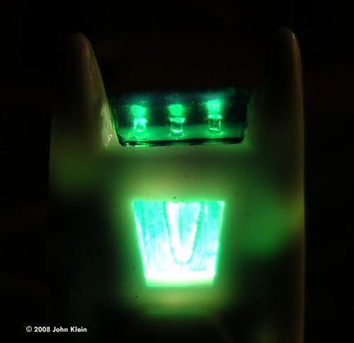
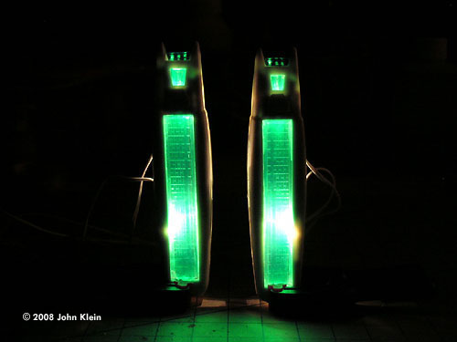
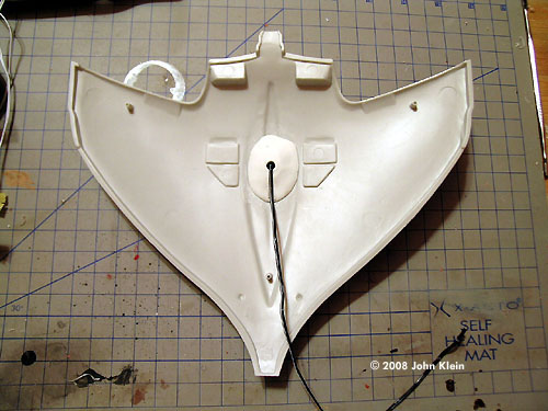
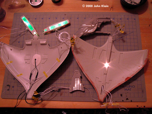
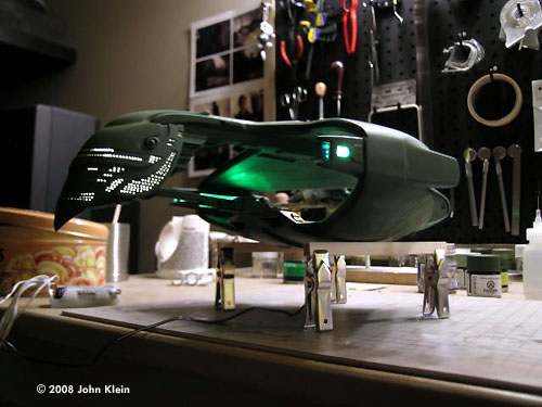
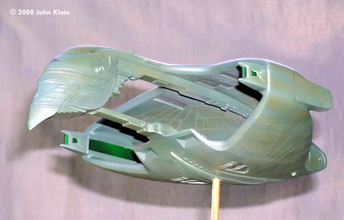
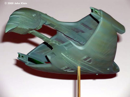
Lighting Rig and Sub-Assemblies This kit is best built in sub-assemblies and since I wanted to include internal circuitry I had to design this in at this point as well. I found a wiring harness with pre-attached bulbs and battery carrier at a model train shop and used this as the starting point for the lighting rig. As I built each sub-assembly I cut the required number of lights away from the harness and numbered each lead for re-attachment during final assembly. Bridge The bridge sub-assembly is comprised of two halves which mirror each other and are to be attached down the centre line. I wanted to keep the rows of windows fairly uniform so I made a guide out of plastic card which I scored in even rows and then drilled out to serve as a template for the window layout. This allowed me to keep the rows straight by following the scored lines without having to score the surface of the model itself. When one half of the bridge assembly was drilled out, I just flipped the template over to serve as a guide for the other half. Since I wasn't planning to run fibre optic filaments to each individual window, merely to fill each window with clear resin, I decided to just suspend a couple of bulbs in the centre of the bridge section. I heated and bent a section of plastic tube and glued it in place at the top of the bridge section to act as a conduit for the wires. I then painted the inside of both bridge pieces with shiny metallic paint to cut down on light leakage and to scatter the light within the hollow space inside the assembly. After double-checking the circuit I glued the two halves of the bridge together and finished them with the usual puttying and priming routine. Tail Section I approached the tail section in a similar manner as the bridge; by first creating a template for the rows of windows and flipping it over to maintain symmetry on both sides of the piece and painting the inside with metallic paint. Due of the thinness of the completed assembly I was concerned about light leakage since the bulbs were in direct physical contact with the inside surface of the part. I addressed this concern by backing each bulb with a small piece of aluminum foil to act as a light block. I flowed a substantial amount of Future Floor Polish around the bulb and wiring to hold them in place; Future dries rock-hard and doesn't obscure any of the bulbs' light. I then checked the circuit and sealed it inside the two halves of the tail section. Engine Nacelles The engine nacelles received essentially the same treatment as the tail section in terms of lighting. Again I used aluminum foil the block light leakage and Future to hold it all in place. I ran three fibre optic strands from the light source to the tip of the nacelle as it was too small to fit a bulb within the front enclosure; I then mushroomed the ends of the strands to disperse the light. The nacelles are fitted with three clear parts each and I pre-painted these with Tamiya clear green with a few drops of Tamita Copper mixed in. The large clear side pieces and the small squarish pieces directly if front of them fit reasonably well and only required a few coats of Future to blend them in to the nacelle after gluing. The clear piece which caps the nacelle tip, however, exhibited very poor fit and needed to be filled in with numerous coats of white glue to blend it in with the rest of the nacelle. After the glue dried, I blended the clear piece in with yet more Future. After giving the outside surfaces of the clear parts a second coat of clear green/copper I masked off all the clear parts and primed the assemblies. Hull The lower hull remained basically unmodified in terms of lighting. I added a piece of plastic tube to the lower section of the hull to receive a brass tube stand. I built up the area around the hull/tube joint with epoxy putty for added strength. A two conductor connector was fed through the bottom of the hull so that the completed model could be removed from its base and power supply if needed, the supply wires leading from this connector were simply glued to the inside of the hull to keep them out of the way. The supply wires feeding the nacelle, bridge and tail circuits were all secured along the spine trench of the upper hull and kept out of the way by covering this trench with a strip of styrene. A hole was also drilled through the bottom of this trench and the “spotlight” which illuminates the inner area between the two hulls was positioned so that it protruded through the surface just enough to cast a beam onto the lower hull. It was secured and faired in place with superglue and Future. After checking the circuit, I flowed massive amounts of superglue into the cavernous joint between the individual hull pieces. The gap between the sections of hull is so vast I'm convinced that the molds for these parts were made by two different mold makers in two different shops with two different sets of drawings. After sanding down the cured superglue I applied the first of many layers of putty and began the process of blending the hull edges together. After the joint was sanded to shape, I applied a few layers of Mr. Surfacer 500 to blend the putty in with the surrounding plastic. This is the first time I've used Mr. Surfacer I found that it's a fantastic product. Applied over putty, it helps to feather the join line between the putty and the plastic. Final Preparation of the Subassemblies Once the six sub-assemblies were primed, I pre-shaded all the recessed areas with black paint to impart a scale effect to the finish coats of paint to follow. I painted all the sub-assemblies with Tamiya Euro Green as a base coat and sprayed the recessed areas with a darker mix of the same colour. I also streaked the central area between the upper and lower hulls with various shades of green and grey as it would have been too difficult to airbrush that area after final assembly. Final Assembly and Finishing Once all the sub-assemblies were dry, I temporarily connected all the circuits and tested the completed rig. I was satisfied that the circuit was complete so I connected all the sub-subassemblies with super glue. After sanding down the dried glue, I puttied and sanded all the joints. Again, the hull joints were horrible and required a considerable amount of work to blend the engine nacelles into the fuselage. After priming all the joints and sanding out any flaws I again used Tamiya Euro Green to basecoat the joints. Then I airbrushed various shades of green and drybrushed the entire fuselage to bring out the highlights. I used various still of the shooting miniature as reference while painting and decided to tone down the garish weathering displayed by the studio model to a finish more like what was seen on screen. Once everything was dry, I removed the masking from the clear parts, filled each window hole with Micro Crystal Clear and then overcoated the entire model with Future to blend it all together. I then applied the only decal (the Romulan Star Command insignia on the nose) and sprayed the fuselage with Gunze Sanyo Dull Coat. I mounted the finished model on a simple base which I made from an inverted mahogany drawer organize box which houses the battery holder, I/O switch and brass tube stand. I finished the base off with a Romulan Star Command symbol which I found on-line and printed onto photo paper. Conclusions This is a fine kit given its vintage and with a little work and a lot of putty can be made to look quite decent. Its lines and detail are very accurate and it's still widely available. |
![]()
This page copyright © 2008 Starship Modeler™. First posted on 9 July 2008.
![[Please click to enlarge]](jk_ddrex_30_Wiring1.jpg)
![[Please click to enlarge]](jk_ddrex_07_LightTest-Bridge3.jpg)
![[Please click to enlarge]](jk_ddrex_19_TailWindows.jpg)
![[Please click to enlarge]](jk_ddrex_11_engines.jpg)
![[Please click to enlarge]](jk_ddrex_25_UpperHullWiring_03.jpg)
![[Please click to enlarge]](jk_ddrex_starfield_2.jpg)
![[Please click to enlarge]](jk_ddrex_VentralAspect_03.jpg)