
|
By Jack Brunner, Jr - images & text © 2005 The AMT/Ertl kit became an interesting project. After opening the box and looking at the hull halves, I could tell this kit was just begging for an interior. Why Ertl never offered some half decent innards is a mystery, but scratch building one is not that tough. Getting Started Refer to the Deep Space 9 Technical Manual for some excellent schematics of the Rio Grande's interior. |
![[Click to enlarge]](jb_runabout_b.jpg) |
|
Image: Bulkheads divide the interior sections Image: Ceiling light test Image: Various light panels Image: Conference table Image: Interior ciming along Image: Lots of fiber optics Image: Holes drilled for nacelle wiring Image: Electrical bus Image: Sealing up the hull Image: Putty required Image: Impulse grill cut-out Image: Inside the warp nacelles Image: Bussard scoop light 'dish' Image: Lighting test Image: Flight deck coming together Image: Painting different panels Image: Opening the impulse intakes Image: Pylons installed
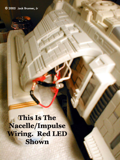
Image: Impulse wiring Image: Warm red glow Image: Exhaust port Image: Detail painting Image: The result Image: Light weathering Image: Nacelle streaks Image: Peeping Tom Image: Pilots Image: Flight deck |
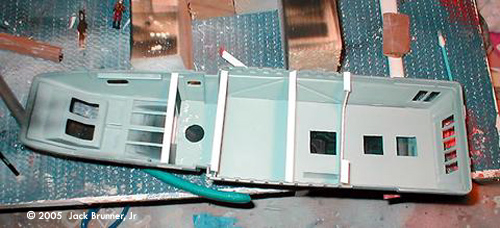
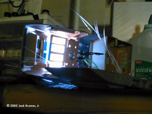
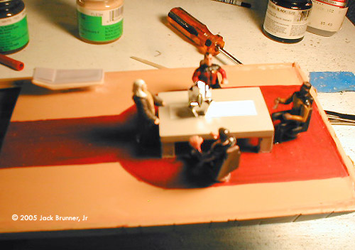
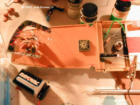
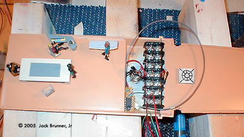
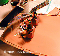
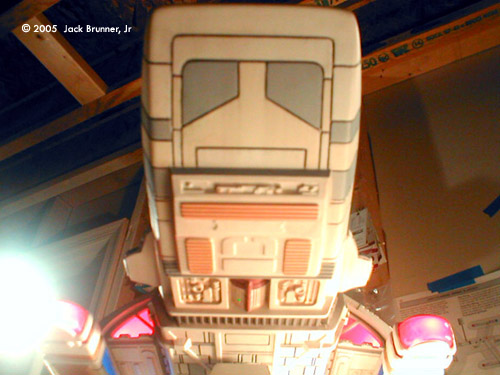
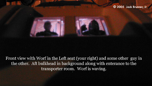
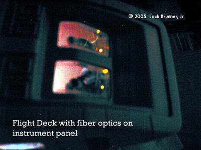
At this point you can make a determination on how complicated you want to make this project. In this article, I will share with you the method I used to achieve an easy, yet realistic interior. First off, you need to segment the Runabout into 5 basic sections: the Flight Deck, Transporter Area, Power Distribution Bay, Living/Sick Bay, and Conference Room. Inset a piece of sheet styrene to fit the interior ceiling from front to rear. Also, do the same to create a floor in the lower half of the hull. The next step of designing bulkhead templates is the most time consuming. Using thin cardboard and a ruler, you eventually find bulkheads that will fit. The bulkheads are held in the hull by using “L”-beam styrene from Evergreen Plastics. On my bulkheads, I elected to get a bit fancy and used both smooth and diamond plated styrene sheeting. The smooth bulkheads are located in the center of the ship with the diamond plated sections separating the flight deck, transporter room, and the conference/living-sick bay area. Lighting Considerations must be given to the lighting panels for the ceiling and the transporter pad. The ceiling panels are installed, along with the bulkheads, and are marked for ceiling panel lighting. The center section of the upper hull ceiling is cut out completely to provide wiring access to multiple LED's. Ceiling panel cutouts are then covered with clear styrene misted with pearl white. Remember to spray your inner hull area Flat Black before permanently installing the floor and ceiling panels. This prevents light from glowing through to the outside of the hull. Numerous lighting panel designs were used. Most interesting out of them all is the transporter room. Here I have 4 small holes which are covered in clear styrene and a round cutout that will support a portion of the transporter illumination. jb_runabout_03.jpg In this picture, you can see where I used a concaved piece of Chrome LEGO. This fits a 3mm LED inside perfectly! The transporter pad is actually a clear square piece of LEGO. Again, a 3mm LED (yellow) fits into the bottom of the square nicely. Most of the lighting on this model is done using 5mm LED's. For the ceiling panels I used clear LED's rated at 3600 Mcd. The main power supply is a 9 volt wall adapter. The LED's are wired in parallel and each LED has either a 270 OHM or 330 OHM resistor attached to it in order to drop the voltage to the LED. The conference room in the aft section has 3 5mm Clear LEDs; one for each ceiling light. The Flight Deck has 3 5mm Clear LEDs for laid out 3 abreast for those ceiling panels. You can also see 4 small holes drilled into the ceiling panel of the transporter room to enhance the illumination of that compartment. Building Up the Interior Next up was the task of determining the positioning of the conference room table, a sick bay bed, flight deck seating, and instrument panel. Starting with the conference room, I used 1/8” thick styrene sheeting to devise a rectangular table. The legs were made out of 1/8” square stick styrene. People figures and seats were cannibalized from a Playmates E-D play set. The chairs with the arm rests worked well. Fastening them to the floor was no problem by using a motor tool to bore holes into the floor to set the chairs into. Loc-Tite 5 minute epoxy worked well in securing the chairs. An important part about the table is the height needed to meet the figurine size. The best thing to do is place a figure in a seat and measure the distance from the table to the floor so that the knees of the figures fit under the table. One of the figures is standing and is actually a repainted Obi-Wan Star Wars piece. I painted him up to look like an Ambassador with white hair; sort of looks like Edgar Winter for all you old rock and rollers out there. Flight deck preparations become a bit tricky. Remember that an instrument panel needs to be installed. In order to do that, small strips of “L” shaped styrene must be set around the sides of the flight deck wall. The instrument cluster is more of a horseshoe shape. That was cut out of thin styrene sheeting and after a few trial fits, I finally found the correct angles needed. Importantly too is the fact that if you should choose to build another-make templates of everything! The seating arrangement is done by trial and error by dry fitting the upper half of the hull over the bottom to see how figure look with respect to the windshield. Fastening the chars is the same as discussed in the Conference Room assembly. Fiber optics are threaded through the instrument pane to give it a touch of realism. The instruments on the panel are nothing more than reduced panel images printed out onto sticker paper. A micro fine dill bit in a pin vise is used to make the holes in the panel for the fiber optics to fit through. On this particular model, I ran the fiber optic bundle through the lover deck flooring. My suggestion would be to run this bundle from the overhead ceiling. It makes life so much easier for the hull mating process. This was part of the learning curve. More Lighting Once I was satisfied with the interior set up, I went into the impulse and warp nacelle lighting. Don't seal up you hull halves until you have the main power wire set up for the power plants. Drill about a ¼” hole in the upper hull portion. Add enough wire to extend out into the nacelles (the furthest point). Impulse engines are powered by one red LED and the power line may be a bit shorter since this portion mounts closer to the main hull. Now after that has been achieved and you have marked all you wires as to what they are for, you can connect all your internal wiring to the Bus Distribution Bar. A “master” negative and positive line run to the power jack. One half of the Bus Bar will be assigned to negative leads and the other half to the positive sides. This choice is yours. |
|
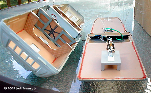
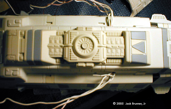
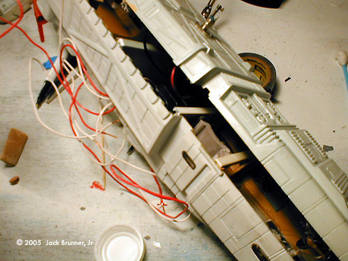
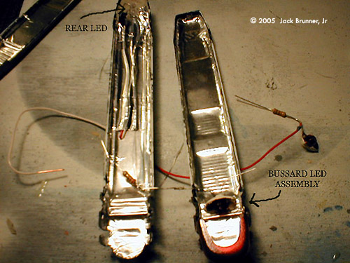
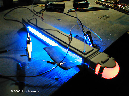
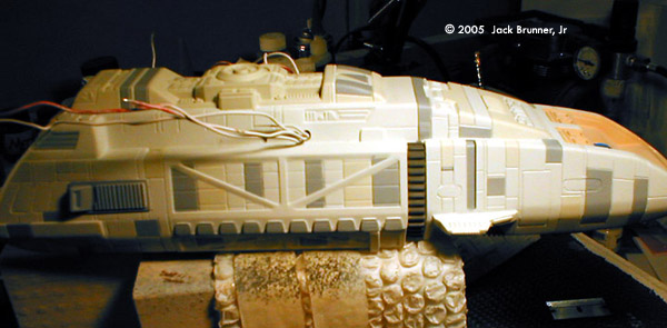
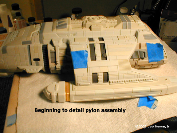
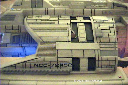
Major Assembly After you are absolutely sure and satisfied with you wiring and you have all the windows, figurines, and your instrument panel secured, you may proceed to seal the hull halves together. This is the fun part. Have plenty of thick rubber bands handy because you will need them. This is one of major flaws of this kit! I've built 3 of these so far and just dry fitting the hull halves together, minus the interior, prove frustrating. Not one of the 3 fit exactly the same. After the hull has been put together, break out the putty. You will need to do some work along the sides; sealing gaps wherever they may appear. While this dries, you may elect to cut out the impulse grill in preparation for connecting the nacelle wiring, impulse wiring, and finally the installation of DLM's Impulse Intake. But we will get to that part a bit later. There are some important things to do inside the pylons. Back to the Engines Again, spray your interior portions flat black to help prevent light leakage. I like to use Aluminum duct tape to line the interior of the pylons for maximum reflectivity. There is an impulse exhaust port that mounts on the rear of the pylon. You should cut or drill out the center of the exhaust portion and fill it with either clear resin or Loc-Tite 5 minute Epoxy. This will allow a red glow to emit from this exhaust port. You can see this in the photo looking though the front grill area, which has been cut out, and into the rear pylon area. Be sure to drill a hole at the top portion of the pylon where it will mate to the hull. This will allow you to feed the wiring into the pylon arm for your engine and impulse illumination. Also, a hole needs to be drilled from the nacelle to the pylon. You can do this by dry fitting the top nacelle half onto the pylon arm. The builder may also elect to use a micro-mini as a running light on the aft nacelle. Once your hole(s) are drilled in the nacelle you may begin using the Aluminum duct tape to line the nacelle innards. The grills were painted Transparent Blue and the Bussard Dome was done in Transparent Red. On each engine nacelle, the Bussard lighting was set up using the most up to date technology available - a piece of Lego! A lampshade type piece of Lego will accommodate a 3mm LED with no problem. Add one of those Lego red circular caps and you have a nice Opaque red glow for your Bussard. In this picture I have lined the dish with a piece of Aluminum for. Cut both sides of the Lego down to make it oval. Insert your LED and then seal the area around it with More-Tite Window Caulk. This is rope type putty that I religiously use on every build to seal bulkheads, firewalls, and anything that has a LED around it. You can find it or something similar at any popular hardware store. Grill lighting was done using a Blue 3mm LED rated around 2500Mcd. The Led was mounted in the rear of the nacelle and pointed forward. Once the wiring is done and before sealing the nacelles, test the lighting. Ertl's Grills are a royal pain to install and have a tendency to fall inward easily. The best approach to this problem is to carefully glue them bottom in first with CA. Strive to set the grills upright to the best of your ability. CA does haze clear styrene so be careful not to glob it on the edges. Give the grills a few minutes to set up and then do a dry fit of the top half of the nacelles. With any luck, the grills should line up with the upper nacelle. Again, CA the top portions of the grill carefully and seal the nacelle. Small rubber bands will provide adequate pressure. With much patience and a steady hand you can eventually line up the grills, insert the Bussard Domes, and seal both of the nacelle halves. Painting Begins Take a break from the lighting and sand down the putty on the main hull. I use a combination of 220 grit and finish up with 1000 grit wet-dry paper. After all the imperfections are taken care of, mask off all windows to prepare to prime the hull. I use Rustoleum's Painter's Choice sandable White Primer. This is a good wet and dry sanding type of primer. You will need a few coats to achieve some nice results. The main goal right now is to paint the side panels of the hull and apply any “weathering” you deem fit. The main reason is due to the small gap between the Pylon and the Hull. It's just big enough to see through but not big enough to do any detailed painting. Airbrush your model with a base coat of MM#4765 Light Grey. As for paneling , I use MM#4761 Dark Ghost Grey and MM#4766 Cammo Grey. Weathering was done using Earth Tone Pastel chalks, finely ground and applied with a wide brush - streaking from front to rear (this is important). Panel lines are done using a mechanical pencil and a toothpick. Run the pencil along the panel lines and follow through with a toothpick to insure getting the lead down into the recessed lines. The segmented strip behind the side phaser bank was done in MM Panzer Grey. In the second Runabout build that I've done, I found painting as many panels on the front, sides, and top actually started to bring out the beauty of the model. The side phaser banks will require some attention also. The undersides are “hollowed” and should be either filled in with putty, or you can cut a piece of thin styrene to cover the area. I chose to do the latter since it thickened the phaser bank a bit more. Either way you chose to go on this, do it before you put it on the model. More Assembly Now it is time to look at mounting the pylons onto the main hull. The fit is rather good with one exception. Remember, there is a gap between the pylon and the hull and it is approximately 1/8”. Both sides should be equal. On both Runabout's the right pylon had a tendency to “hug” the hull. You can place a spacer between the pylon and hull to remedy this. Be sure to feed the wires from the hull into the pylon and bring them out through the grill area that was previously cutout. Now you can proceed to wire up the Nacelle, Bussard, and Impulse lighting. I chose to place my resistors inside the pylons since the junction of the engine to hull power was at the pylon area. The impulse area is illuminated with a 3mm Red LED rated at 1300Mcd. Much of the wiring slack that you see is trimmed down before the connections are all soldered. Stow the wiring into the pylon assembly. It would be best to position the Red LED perpendicular to the opening. This will allow the light to evenly spread throughout the pylon thus illuminating both the Impulse Grill and Exhaust areas. Remember, the Aluminum duct tape works wonders for reflectivity. Next, dry fit the DLM Impulse Grills to check for proper fit and then use CA to fasten them. These are resin parts and regular Testors glue will not work. After you have fastened these you may need to do a small amount of putty work to close the seams. As much as I try to avoid using Squadron putty, Squadron White is the best bet here. Use sparingly and apply with a small flat-bladed Xacto knife and/or toothpick. Squadron putty is tough to sand so don't use too much. I chose this white putty since I wouldn't have to apply coats of primer necessary to cover the Testors Red Putty. Bring It to Life With the majority of the hard work done, it is now time to bring the vessel to life with the color scheme. For me, it is impossible to be 100% canon with any of the Trek models that I build. But I do find that sticking as close as possible to the colors plus using some imagination really helps. Mask off all windows and illuminated areas of the pylons and nacelles before airbrushing the base coat of MM#4765 light grey. Airbrushing this model is a piece of cake and the most enjoyable of all. Masking off panels is simple. If anything, the toughest part might be drawing in the recessed panel lines; but even that is fun. Additional detailing to the dark grey area of the pylon and top of the hull can be accomplished using a very fine artist brush to paint tubing and smaller modules. Dry brushing techniques can also be used. When you completely finish airbrushing your panels and drawing in your panel lines, its time to add some weathering effects. Again, ground up earth tone pastel chalks was used. I find that taking the chalk stick and running it across some 220 grit paper gives you a nice texture. I use a short medium width bristle brush to apply the grindings in a fore to aft motion. Then I follow up using a soft bristle brush, moving from fore to aft. You can clean any excess chalk grindings by using your airbrush to blow air across it or by just plain blowing on it. The amount of weathering on the model is strictly your choice. You can go from the “fresh from the factory” look or make it look like it went through a B'joran mud storm. It's a personal preference but one you should use with prudent judgment. The final step before applying the decals is to seal the model with a good dull coat. Some may choose gloss or even Future floor polish. It's all up to you and how you want your end result to look. It is now time to pull off the masking tape. Use a Xacto knife to assist in removing tape from hard to get areas. The decals that come with the kit are horrible. I decided to use custom aftermarket decals from JT Graphics. The accuracy and detail of these decals are impeccable. A good tip is to put a drop of Elmer's glue in the water and mix it up before using it to soak the decals. This helps to eliminate that “silvering” look of the decal once it dries. A good decal setting solution is also recommended. Just take you time when applying the decals. There is nothing worse than a great paint scheme and a sloppy decal job to ruin it all. Finishing Touches Power is supplied to the model via a 9 volt 800ma wall adapter. I run the line up through a brass tube that houses an epoxied male jack at the end. This inserts into the belly of the vessel and provides a 360 degree swivel for viewing during illumination. The power jacks can be picked up at Radio Shack. I custom build 4 sided pyramid type stands for almost the entire line of Trek ships. Some stands rest on an oval wood base or on a rectangular box; for those interested in sound effects. For the sound effects I use a 20 second sound card per each effect. Activation buttons are then placed on the base and covered with a custom made LCARs panel. But the stand, base, and sound effects are another article in itself. |
![]()
This page copyright © 2005 Starship Modeler™. First posted on 23 March 2005.
![[Click to enlarge]](jb_runabout_c.jpg)
![[Click to enlarge]](jb_runabout_a.jpg)
![[Click to enlarge]](jb_runabout_d.jpg)
![[Lit]](jb_runabout_e.jpg)
![[Click to enlarge]](jb_runabout_f.jpg)