
By Steven S. Pietrobon - images & text © 2005
|
![[Click to enlarge]](sp_r2d2.jpg) |
|
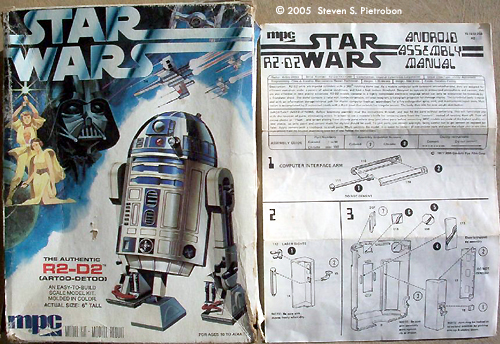
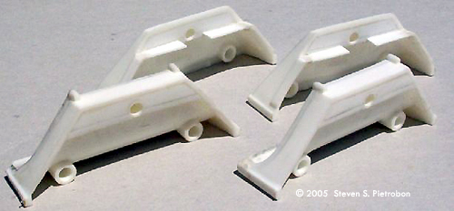
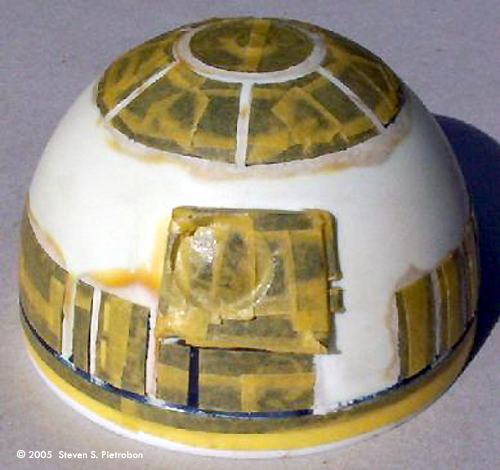
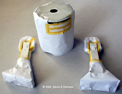
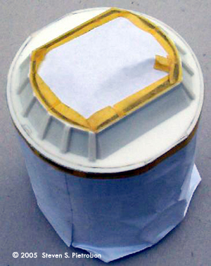
Image: Box and instructions Image: Side feet slotted and plastic card added. Image: The front foot shows the plastic card added to the front, top and back. The back foot shows the plastic card inserted at the side. This was latter trimmed, with any gaps filled in with putty. Image: Spraying indoors is not a good idea. Here, I'm about to spray the body and arms mindnight blue. Image: The blue panels on the dome masked up. Image: The body and arms masked up. Image: Bottom masked up. Image: "We're not interested in the hyperdrive on the Millennium Falcon. It's fixed. Just tell the computer to open the door!" Image: A rare view of the reactor (top) and computer (bottom) inside R2-D2. Image: Right side |
I bought the MPC R2-D2, along with C-3PO, Luke Skywalker's X-Wing, Darth Vader's TIE Fighter, and the Millenium Falcon, in a sale at a department store in the city around the end of 1980. I remember walking home excited with the kits in my hands. As soon as I got home, I opened them up and started planning on building them. My first project was R2-D2. I had a few magazine clippings and it soon became apparant that the kit was not very accurate. I decided to make it accurate, buying some plastic card, razor saw and liquid glue which I had never used before. The Summer of 1980/1981 was partly spent building R2-D2, but there were so many changes, I couldn't keep up the commitment to finish the kit. With school holidays finishing and Year 12 starting soon, R2-D2 was abandoned half built in its box. I next worked on the kit in the Summer of 1984/1985, while I was doing work experience at Thorn-EMI for my Bachelor's degree in Electronic Engineering. I even wrote down the date that I last worked on it in the inside of R2-D2's head, 11 January 1985. I did some work on the head, sanding and filling gaps. Time passed and 24 years after I bought the kit, I decided that I was going to finish R2-D2. By pure coincidence, I finished R2-D2 a few days after seeing Revenge of the Sith in the cinema. The instructions or "Android Assemble Manual" consists of 14 easy to follow steps. The kit includes stickers. As the kit was to be fully painted, these were not used. The instructions include many names of parts, which I use here. Here's the list of corrections that I performed:
|
I had planned on including lights for the dome, but as I wanted to get the kit finished, this idea was abandoned. I was just glad that I was finally finishing the kit! Painting The body, arms and middle leg were sprayed first with undercoat grey (Humbrol 1) and then with satin white. The Humbrol paint I used was not a pure white, but a bit off-white which is annoying. It would have been better to use matte white for the undercoat, as the satin white would often chip around doors, showing the grey underneath. I couldn't just spray the dome blue, as this would cover up where the blue panels should be. So, I first masked up the non-painted silver area first and sprayed the dome midnight blue (Humbrol 15) which is a very dark blue. I chose midnight blue, as it matched the photos I had. Watching the films though, the actual blue can best be described as "candy apple blue", like "candy apple red" used on cars. This type of paint changes colour depending on the angle and lighting conditions. It might have been more accurate to use French blue (Humbrol 14) which is a normal blue colour, but I think midnight blue looks better. After spraying, I found that there were nearly always small bits in the paints surface, so this had to be sanded down and resprayed. Thus, instead of only one or two coats, I was giving three or four coats. This greatly increased the time to build the model. One cause of the problem was in not fully removing the skins from paints. If the skin is thick, it is easy to remove, however if the skin is very thin, its much harder to remove. The other problem was spraying indoors where there is lots of dust. After deciding to spray outdoors, this problem was greatly reduced, plus I don't stink up the house! The blue parts of the dome were then masked up. I decided to brush paint using my trusty 25 year old silver (Humbrol 11) paint. I believe this gives a more realistic finish, as long as you don't look too close. The white areas on the body and arms were masked up and sprayed midnight blue. The reactor and computer were sprayed with undercoat grey and then satin white. The bottles were painted midnight blue, with the hoses matt red. The two round fins were painted silver. Minor detailing with silver and matt black was then done. Due to the new walls constructed from card, it was difficult getting this part to fit. The back door was detailed with silver, midnight blue and satin black. Detail painting was then performed. I used matt grey and matt black for the side vents. Aluminium was used for the vents. For the dome, the front "infra red eye" was painted gloss red and the rear "eye" was painted gloss white, followed by gloss yellow. To make up a mask I would put some Tamiya masking tape on a flat surface. Using a round stencil, I would then use a pin to slowly scratch out a hole. The middle round mask would be removed leaving the masking tape with a hole. In The Empire Strikes Back, the front eye would alternate between red and blue, while the rear light alternates between yellow and green. These lights were static in A New Hope. The Speaker/Microphone (below Tool Arm) was painted dark green, while the Pressurising Vents (below Speaker/Microphone) was painted semi-gloss black. The edges around these were painted silver. The base of these was painted midnight blue. The programming controls were painted aluminium. For the two rectangle lights at the front and thin rectangle light at the back of the dome, I first painted a sliver edge, masking the inner and outer part of the light. Masking the silver edge, the centre was painted with a mixture of silver and midnight blue, to get a metallic light blue effect to simulate the lights. The silver pin striping around the shoulders and halfway up the arm was done by first masking and painting silver. This came out much better than I expected. The round shoulder attachments on the body were also painted silver. The energy cables from the power pack to the feet were painted using a mixture of brown paints (I can't remember exactly what I used). Final Assembly After the middle leg was completed, it was put into the sliding mechanism which was painted matt black. This was then glued into the body. The bottom plate 25 was then glued in place, with plenty of filler to fill in the gaps. I used liquid paper for the first time to fill in the very small gaps left after filling. After masking, the bottom plate was sprayed satin white. I then made up some decals which you can download here. You will need GSview to print this file. The short grey segments are used for the front and back of the feet. You need four segments per side. The long grey segments are used for the sides. You need seven segments per side for the two side feet and five segments per side for the middle foot. The small black segments are for the buttons on the Programming Controls. The dashed black semicircles go near the base of the arms and middle leg. It took me three goes to get the decals right. On placing the first decal, I found that I had printed it on white decal paper! Printing the fourth time on clear decal paper, I found the decals went on well with some setting solution. |
|
|
The arms were superglued in place, as the small parts 19 could not be used to hold the arms. After drying, the arms moved smoothly, but not as far back as on the real R2-D2. With the middle leg pushed into the body, R2-D2 can stand on two legs, if a little unsteadily. The dome nicely rotates. I almost expect the model to beep and move around! Conclusion After nearly 25 years, I have finally completed my R2-D2! The MPC kit seems to be basically correct in shape, but if you want to get it actually looking like R2-D2, you have your work cut out for you. The Kaiyodo 1/6 vinyl kit is much more accurate, but I believe it doesn't have anywhere near the number of working features of the MPC kit. |
|
![]()
This page copyright © 2005 Starship Modeler™. First posted on 2 June 2005.
![[Click to enlarge]](sp_r2d2_front.jpg)
![[Click to enlarge]](sp_r2d2_parts.jpg)
![[Click to enlarge]](sp_r2d2_body_arms_head.jpg)
![[Click to enlarge]](sp_r2d2_mask.jpg)
![[Click to enlarge]](sp_r2d2_paint.jpg)
![[Click to enlarge]](sp_r2d2_back.jpg)