
|
By Jim Kiker - images & text © 2006 The Headhunter FR 17 was developed to meet a requirement for a new Fleet multi-role fighter formulated by the Self Defense Forces of Solaris III. This requirement called for a relatively inexpensive design which could handle the fighter, fighter-reconnaissance, and light strike roles. The new fighter would be based upon proven technology, yet be able to hold it's own with more modern types. In addition, it needed to be capable of extended operations in atmosphere as well as space, and be capable of limited hyperspace jumps. |
![[Please click to enlarge]](jk_z_hunter_Image1.jpg) |
|
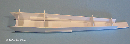
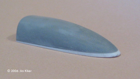
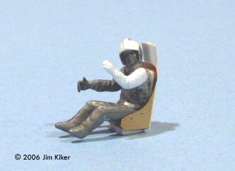
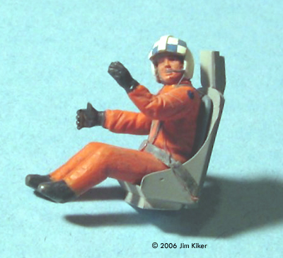
Image: Starting the fuselage Image: Canopy plug Image: Pilot Image: Now he looks properly "Star Wars-y" Image: Wing pieces Image: Engine pieces Image: Ready for paint Image: Completed model, underneath |
The Z-95 Headhunter II technology was chosen by the engineers at Space Dynamics as a basis for their new design. The wings were extended, tapered, swept back, and given an airfoil shape. Small canards on the forward fuselage proved to be needed to optimize the fighter's atmospheric flight characteristics. FR 17's are powered by four Incom 2A-E (Enhanced) engines. The 2A-E engine is an upgraded version of the basic design, featuring a slightly larger main engine and full axial flow. These engineering tweaks yield approximately 10% more thrust, so the FR 17 gains nearly 40% more power and significantly higher top speed. "Red 2" from the 18th Squadron is typical of the FR 17 in Solaris Fleet service. The reconnaissance equipment includes four planar imaging arrays, one on each side under the canards, and two arrays on the forward lower fuselage. When coupled together, these arrays provide horizon-to-horizon scanning, while the two lower arrays can also be set to provide full stereoscopic imagery below the craft. An integrated infrared sensor oriented to scan below the vehicle completes the sensor suite. Background A few years ago I ran across references to the Z-95 Headhunter, a precursor to the much more famous X- wings. Later on I discovered that Zarkus Models had produced a 1/48 scale Z-95 kit in resin. I found pictures of one and decided that it might make an interesting project. At the same time, I began thinking about changing the design a bit, perhaps by adding swept wings to the basic kit. After reviewing the kit and thinking about how best to approach the project, I decided to go for a full scratch build. I used published drawings as a starting point, changing the bottom to one flat piece rather than a two-piece angled surface. Although my dimensions are otherwise close to the original plans, I did lay out and draw a set of plans for myself. This allowed me to take measurements and accurately mark and cut all the plastic pieces. I also felt that, based on my drawings, this fighter would need the canards added to make it more maneuverable in atmosphere. Construction Making the fuselage turned out to be a complex process for me. I measured and cut out four bulkheads from .040" plastic and then cut out the bottom and lower fuselage sides. All of the fuselage pieces were made from .040"sheet plastic. I measured the locations for the concussion missile launchers and cut openings for the launch tubes in the sides. These launchers should have the launch tube straight and parallel to the ship's centerline. This requires a fairly long tube, with a longer opening on the side of the fuselage than commonly seen on Headhunter and X-wing kits. Once the tubing was solidly in place, I sanded the protruding sections back flush with the fuselage. |
|
Like the X-wings, the Headhunter uses repulsor lift during take off and landing, and I wanted to show some kind of appropriate surface. I cut two openings in the bottom of the fuselage, backed them with sheet styrene, and added rows of strip plastic to represent directional vanes. Once the ship was being painted, I masked these lift openings off and painted them "scale black" to make them stand out. The main landing skids and struts are contained in bays in the rear of the fuselage instead of in the engines. As my ship is shown in flight, I merely scribed panel lines for the closed main landing gear doors into the bottom rear corners of the fuselage. The back end of my Headhunter is somewhat simplified from the kit pieces. I reasoned that a large hatch would make maintenance in the fuselage below the generator cowling much easier, so I laid out dimensions to fit between the landing gear bays. I used .015" strip to create a raised lip around the door's shape, and added plastic half-round rod to form a larger hinge along the bottom. Some additional strip material provided some raised relief around the main access hatch. Moving topside, I felt that the pilot really should sit farther forward so he can see a little back over his shoulders. Sure, sensors to view his six o'clock are part of the sensor suite, but when you're close in, if you can't see your bogey you become dead meat. I also wanted a cockpit that comes closer to my idea of a space fighter cockpit. To provide more front-end headroom, I started with the kit's resin canopy piece (and I'm grateful it came in the kit along with two vacuformed canopies) and added a wedge of .060"plastic sheet on the front end. Tapering this piece from front to back with the full thickness at the front end raised the front of the canopy and provided more headroom toward the front, while retaining the same attachment at the rear end. I then glued the upper rear generator "egg" shape to the canopy to form one piece. I sanded off and filled in all of the detail on these pieces, then heavily primed, sanded, and polished the completed assembly. I then vacuformed a new unit from clear .020" PTG plastic. This plastic is stiffer than butyrate, but I wanted it that way so I could scribe panel lines in later. The PTG developed some pits and marks during the heat forming process, so I sanded the canopy inside and out, polished it, and treated it to a dip in Future. Working vehicles generally do not have really sparkling canopies, but in this case the PTG plastic really needed the Future coating to come back to being fully clear. The interior started out as a spare resin jet aircraft cockpit tub. Considering that the instrument panel should be close enough for the pilot to reach without leaning forward, I figured out where the panel needed to fit. This established where the seat needed to be, and in the end the pilot sits significantly more forward than the standard placement. This gave me the improved rear visibility I wanted. The cockpit is equipped with a HOTAS (hands on throttle and stick) arrangement similar to an F-16 layout, and the seat was built up from a spare PE (photoetch) seat shape with scratchbuilt details. The instrument panel and part of the coaming over it were scratchbuilt from sheet plastic. The panel was laminated from two layers of sheet, with the main displays cut out of the top layer. I added a few bits of strip to busy it up a little, then painted it. The back layer was painted in "CRT blue," then "displays" were scribed in the paint, revealing the white plastic. It looks pretty good when complete. Clear acrylic gloss gave these displays a bit of shine. The coaming assembly received a piece of reshaped aluminum tubing to represent a holographic "heads up" projector. As for the pilot, I found an old Monogram pilot that looked a lot like what I wanted. I carved off his oxygen mask, repositioned his head and legs, and added new arms to get the pose I wanted. Since his helmet looked far too 1950's, I added bits of sheet and strip to transform it into the Star Wars-style. I added a new seat harness, and presto, I had a good star fighter pilot with crisp details to put under all that canopy glass. I painted the cockpit tub light gray, with the upper surfaces and the coaming in flat anti-glare blue-gray (actually it's PRU Blue from RAF WWII paint colors), then picked out the details in light gray, off-black, and a bit of muted red and yellow. I gave the whole thing some drybrushing and a light wash to show some wear and some dirtiness, and mounted it onto the fuselage top piece before adding that to the fuselage cockpit. With all the main fuselage pieces together, there followed a tedious period of filling and sanding, using my Mark 1 eyeball to make sure I wound up with straight lines along all the angles where pieces mated up. This was more difficult that I thought it would be, since it is easy to accidentally sand in some curves and dips while working the seams. I measured and cut out the pieces for the nose cone and glued them into place, repeating the fill and sand process as needed. I then measured off and scribed a series of panel joint lines, and finished up by scribing some access panels in as well. At the same time, I gave the generator cowling section a light coat of primer so I would have a good surface to work with. Using the pictures and drawings, I laid out the panel lines on the cowling and scribed them in. I cut out and painted the rear bulkhead for the cockpit, including a canopy extension hydraulic assembly (two pieces of telescoping tubing with a few doodads added) and mounted it into the appropriate spot on the cockpit rear deck. I added one more bulkhead inside the generator egg to help it hold its shape, and then glued the whole onto the fuselage. I used Mr. Surfacer to fair in the generator section to give a smooth, easy to finish joint. I gently masked the front tip of the canopy and painted it. I had decided to add an anti-glare panel around the canopy. During finishing I taped off the bottom edge of the canopy and painted the anti-glare panel, again using the PRU Blue. I measured and drew out the framing for both the bottom canopy frames and the opening section on some clear decal film, painted the interior and exterior colors, covered that with the prescribed clear decal fixative, and cut out these frames. They were added after all painting and finishing was done on the rest of the model. This was a difficult area for me to finish well. Since the canopy had been Futured and attached early on, there was only so much handling it could take without taking off the Future, and that would have been a real mess! Next time, I'll separate the canopy and add it after the rest of the painting is done.
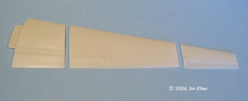
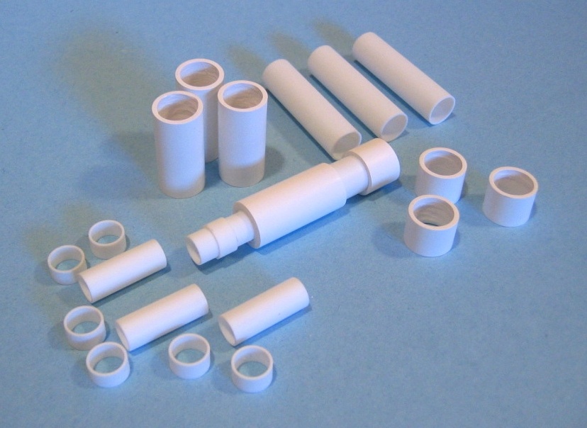
Wings I conducted a search to see if I could find a commercial kit that would provide a basic wing shape for my Headhunter, and I found it in an old Hawk/Testors 1/48 scale U-2 kit. I sectioned a piece out of each of the four wing pieces, giving me a somewhat swept, tapered shape with an airfoil cross section already built in. The trick was to find such a shape that also had the same length from front to back at the wing root as the kit's wings. I filled in and sanded off all the original details and scribed in new control surfaces as well as new panel lines. Later, I carved and sanded large depressions into these pieces near the wing roots (with sheet plastic backing in the deeper top wing depressions) to accept the four- engine layout, as well as smaller depressions for the wingtip blasters. I used the cut-off wing tips from the kit as a starting point for the canards (the small winglets near the nose), cutting, filling, and scribing the needed hinge lines. It would have been easier to make them from scratch from sheet plastic, but then, hindsight is still 20/20! Engines I chose to build new engines using a series of plastic tubing pieces that "nest" inside of each other. A long inner piece of tubing served as a backbone, to insure that the pieces would easily build into a straight line. After laying out the dimensions, I cut enough of the various sizes of tubing to build all four engines at the same time. The sections behind the intakes needed bulking out, so they got two layers of sheet plastic strip. The ribbed detail was then created from individual pieces of dimensional plastic strip. The exhaust sections were based on smaller plastic tubing. The dark "finned" sections were created by wrapping and gluing .020" solder around the core tubing. This is one long piece of wire spiral-wrapped around the core. This took a bit of practice to keep the wrapping tight and not leave spaces between each succeeding coil of wire. The engine exhausts had me scratching my head, since they looked quite complicated to create. Remembering that the Headhunter is the older, smaller cousin to the X-wings, I pulled out a 1/72 scale X-wing (the beautiful Fine Molds kit) and found that the kit exhausts mated perfectly to my exhaust tubes. This was pure serendipity. I also received a spare X-wing kit from one of my model geek buddies (thanks, Wedge!). That gave me a kit to rob parts from and a complete X-wing kit to build later. As it turned out, the "splitter plates" in the engine intakes from the kit also fit right into the new engine intake parts I had made. I wound up using several sets of detail pieces from the X-wing to make my scratch building a bit easier. Access panels on the outer engine casings were measured and marked off and the panel lines and fasteners were scribed in. Some thin plastic strips were added near the back end of these main casings to retain a visual cue from the X-wing and Headhunter detailing.
It Finally Comes Together With the fuselage done the final assembly went more quickly. I slipped the wings over their spars, maneuvered them into position, and glued them into place using both epoxy and plastic glues, and used both epoxy putty and Mr. Surfacer to fill the joints. I added the canards on the forward fuselage and repeated the Mr. Surfacer treatments until I was happy with those joints. I masked the bottom edges of the canopy and painted the anti-glare panel around the canopy, then masked it off to paint the main exterior color. I painted the leading edges of the wings, canards, and nose with silver, then a generic light gray-green color. After painting the vehicle in the primary light gray color, I sanded the leading edges in places. The idea was to show wear along these edges, where the environment has worn off the paint, revealing the primer coat and bare metal underneath. I also mixed a slightly darker shade of gray and masked and painted selected panels (the landing gear bay covers, some access panels, and the like). I added a clear acrylic gloss coat on the entire model to prepare for decaling and weathering. Most of the decals were a custom job, although the pin-up art came from a sheet purchased from Starship Modeler. I originally planned on adding a fair bit of stenciling, but eventually opted to make most of those into symbols, which were either cut from colored decal sheet or stolen from my decal stash. I think that is more in keeping with the Star Wars style. I found a Star Wars font named Aurebesh on the Internet, and used it to make the name of the ship and a few additional items. The blue and white "planetary" markings were masked off and painted separately. After the decals were dry I added another clear acrylic gloss coat, then added oil washes in the panel lines as well as some weathering. I like to use a darker grey wash for the moving flight control surfaces and the main removable engine panels, and a lighter shade for the panel lines on the craft's surfaces. Based on my experience around operational military aircraft, I think that all dark panel lines result in more of a "toy" effect than a working vehicle. I added some additional grime, wear, and tear around the craft's surfaces where pilots and mechanics walk and work. I painted, washed, and weathered the engines separately. The engines were then glued into place using two-part epoxy. Finally, I made up the display base and painted it. I added a piece of painted brass tubing to support the model "in flight," setting the viewing angle to show off the craft's lines. The symbol of the Rebellion is a resin casting from a company named The Model Base, painted in the appropriate colors and mounted on the main base. Acknowledgements
|
![]()
This page copyright © 2006 Starship Modeler™. First posted on 20 February 2006.
![[Please click to enlarge]](jk_z_hunter_Image14topinverted.jpg)
![[Please click to enlarge]](jk_z_hunter_Image6cockpit.jpg)
![[Please click to enlarge]](jk_z_hunter_Image9engine.jpg)
![[Fron/right view]](jk_z_hunter_Image12rtfront.jpg)
![[Right/rear view]](jk_z_hunter_Image13rtrear.jpg)