
By John Boswell - images and text © 2003
|
![[Click to enlarge]](jb_atat/jb_atat_06.jpg) |
|
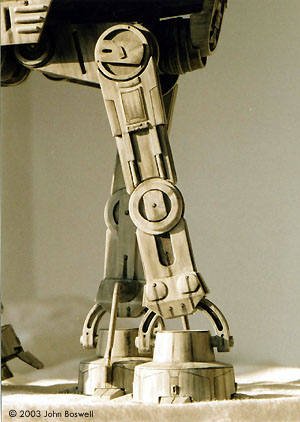
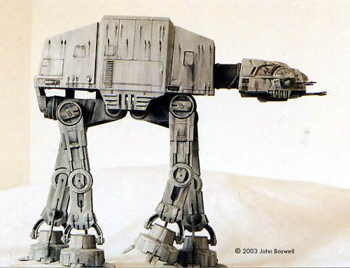
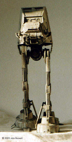
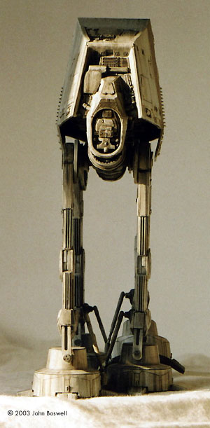
Image: Head detail Image: Leg detail Image: Right side Image: Left side Image: Target's-eye view Image: Rear view Image: Top view |
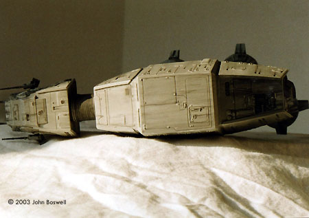
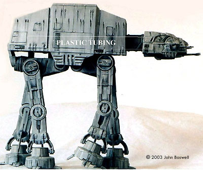
ERTL's AT AT was in my opinion one of their most accurate Star Wars kits. Even if you build it straight from the box you'll get a really nice kit for your money. However I saw the potential for this model to shine and chose to get it as close as possible to the studio miniatures. The kit does have one major flaw though, THE LEGS and MAIN BODY ARE NOT THE SAME SCALE ! The legs are set too close together; if this model were to walk, it would trip up over its own feet ! There are 3 ways you can tackle this problem:
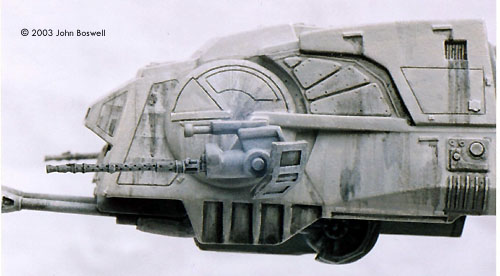
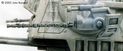
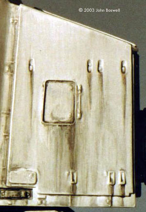
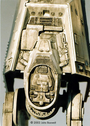
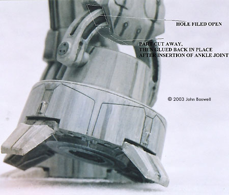
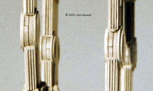
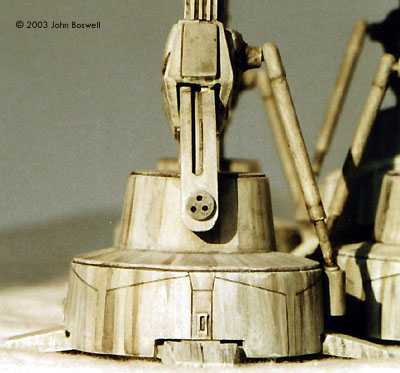
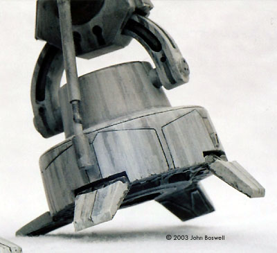
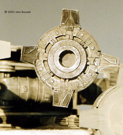
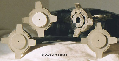
I put a lot of effort into correcting the kit, as follows: Head To give the head strength and stability, I put layers of Milliput along all the joins inside the head. This helps because there are no locating pins and lining up the top, front and 2 sides can be tricky otherwise. I filed open the cockpit slit and put some plastic card painted gloss red behind it. Some panel lines were missing so I scribed those on. For the side guns I cut off the barrel and replaced it with a gun barrel from a 1/35th scale Tamiya soldier accessory kit. The panelled part to the rear is just the kit part with evergreen strip glued on it. The chin guns need a lot more work; they are very inaccurate and clear reference pictures are hard to find. The main part of the barrel is brass rod, then working towards the front its shaped Milliput, very small plastic ring then shaped aluminium tube at the front. The detail underneath the head is a length of plastic tube cut in half, scored to angle them upwards, and then layered in Milliput to get the correct shape. The only original kit part used on the chin guns is the rear most part. Main Body I started by sanding off all the unnecessary raised panel lines and scribed new ones, some detail should be raised and used Evergreen plastic strip to either replace or improve it. The steps at the side are plastic strip again, cut to size and glued flat to the surface; more strips are glued on top at a 90 degree angle. When completely dry I sanded the edges to round them off slightly. The front access hatch needs to be recessed so I used a Dremel to cut the shape out, and then used a sanding drum to thin the plastic on the inside. Use the slowest rpm you can to minimise the chance of the plastic melting. The top also received scribed and raised detail. The back of the main body received no extra detailing as I was happy with the kit part; it's the painting that improves this part. Neck The rounded ends of the neck were sawn off to give a much closer fit to the head and main body. A length of thick plastic tube was pushed all the way into the main body, the neck pushed and glued over it with the head being glued on last. This gave the strongest possible fit for this assembly. Fuel Slugs/Drive Motors The front and rear drive motors needed no modification except for a couple of spacers each to set the legs wider apart. The inside rear of the fuel slug was detailed with bits of sprue and plastic strip. Hip Joints For the hip joints I cut a long narrow groove at an angle out of each one, and then backed each joint with thin plastic card. Make sure you get these the right way round before you cut into them, getting it wrong can really do your head in, trust me! I wanted some detail behind where the legs attach to the hip joints, I used the rear disc brakes from Tamiyas Bimota Tesi kit, I only had three so I used a blank plastic card disc for the fourth leg, I'll let you spot it though. On reflection it would've been better to scratch build the hip joints out of aluminium sheet for greater strength. Legs The legs on the studio miniature have 3 raised ridges running down the front and back of each leg, above and below the knee. I used slightly thicker plastic strip cut to size, when glued in place I cut them at an angle towards the knee joint. The attached ankle joints need to be cut off and holes filed open, and the shaped to accept new re-molded ankle joints. I carefully cut the very bottom of each leg out so I could slot the ankles in place, allowing the cut away parts to be glued back in place. Knees The knee joints were filed out to accept scratch built ones. The new knee joints are 2 thick circles of plastic card separated by a much thinner circle of a slightly smaller diameter. Strips of thin plastic card were glued on top of one circle, front and back to complete them. Ankle Joints These needed to be completely remade. |
|
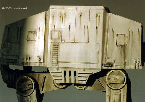
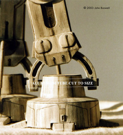
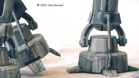
Using the ankle halves from the kit to make molds I made 4 copies. I could use the kit parts on two of the legs so this saved some work. After the molds were cleaned up I cut thick pieces of plastic card to go between them. They are cut deeper to create the trench effect between each half. A hole was drilled through each end so I could slot a length of aluminium rod through each ankle; these were then filled at each end. Those 3 indentations at the front were made by gently hand turning a very fine Dremel engraving bit. A slot was cut into the top of each foot so the completed ankles could be glued in place; the top was then filled and sanded. Feet Before any assembly I glued a 2mm rim of plastic card along the outside edge of each foot. This was to give the toe gaps greater depth. Next was the side bar that connects each foot to the lowest part of the inner leg. This was mainly scratched from aluminium tube of 2 different diameters cut to size, only the top part of the original kit part was used. The locating hole on the foot was removed and replaced with a more accurate one made from plastic tubing. I scribed the detail on each foot - it's the same pattern all the way round and it's the same on each foot. The detail on the underside of the raised foot is mainly an educated guess, using various discs of plastic with bits of plastic strip. Toes The toes need to be angled downward slightly, so I glued a disc to the bottom of each foot and scored the back of each toe then bent them down. When I was happy with the angle I super-glued them in place. The toes on the raised foot are angled to a greater degree to give the illusion that they are hinged, and have weight and mass, but the technique used is the same as the others. Painting The first coat was a spray of white auto primer, sanded back with fine wire wool. I brushed on the first coat of Humbrol light grey and this went on great, it wasn't an overall smooth finish as some areas of the primer showed through, which gave the worn effect I wanted. To weather I dry brushed streaks of light and darker grey, then used various washes of thinned Tamiya flat black to show oil streaks, shadows, recessed detail etc. I used satin varnish over the oil streaks to make them more realistic, (not sure if you can make this out on the photos). Photography
Overall I was really pleased with the finished result: I feel like I've got the real thing sitting on my sideboard! I could have lit the cockpit with a red LED but I just wanted to get the kit finished. I decided not to paint on any snow effects as I plan to build a diorama based on Endor, recreating the scene where an AT AT delivers Luke to Darth Vader. My only main regret with this kit is that I didn't have a camera when building it, would've been nice to have some “in progress” pictures as well. These AT AT kits are hard to find now but if you see one snap it up, you won't regret it! If you have any queries, comments or suggestions about this build up drop me an eMail. Just like to say a huge thank you to my Great Uncle Joe and his son Joe for all their help with the photography, nice one ! |
![]()
This page copyright © 2003 Starship Modeler™.
First posted on 6 October 2003.
Last updated on 6 October 2003.
![[Click to enlarge]](jb_atat/jb_atat_01.jpg)
![[Click to enlarge]](jb_atat/jb_atat_02.jpg)
![[Click to enlarge]](jb_atat/jb_atat_03.jpg)
![[Click to enlarge]](jb_atat/jb_atat_04.jpg)
![[Click to enlarge]](jb_atat/jb_atat_05.jpg)
![[Click to enlarge]](jb_atat/jb_atat_07.jpg)
![[Click to enlarge]](jb_atat/jb_atat_09.jpg)