
|
By Phil Gruver - images & text © 2003 I first saw the TAU Devilfish and Hammerhead vehicles at a hobby store in San Francisco (Japan Collectibles). At that point I knew nothing about Warhammer 40000 (WH40K) nor much about war-gaming for that matter. But the vehicles were really cool and the store had a two-for-one deal going that I could not refuse. Alas, I already had several other models in the queue and it was several months (actually two years) before I got around to building them up. I decided to do a lighted diorama using both vehicles. After toying with alien landscapes using rock formations sold for aquariums, I decided instead to simulate a forward reconnaissance position inside a bombed-out structure. I then read a great article on creating snow scenes with baking soda and, with the end of the year approaching, decided a winter setting was in order. The diorama was completed with a set of fire warriors and 25-year-old greeblies. |
![[Click to enlarge]](pg_tau/pg_tau_fig00.jpg) ^ A Citadel gothic structure encloses an encampment consisting of two Tau hovertanks, a group of fire warriors, drones and some long forgotten greeblies. The scene simulates a Warhammer 40000 winter engagement. |
|
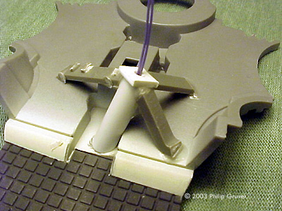
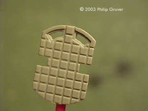
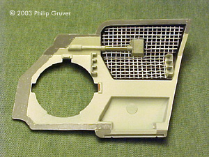
Image: Engine subassembly
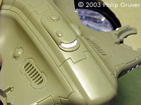
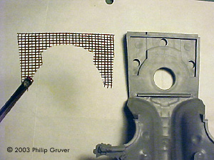
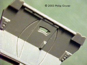
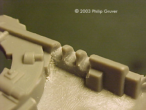
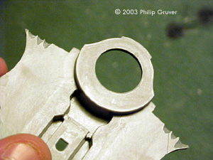
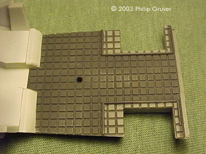
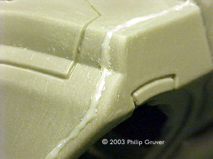
Image: Bulkhead door window cutout. Image: Headlight cutout (chassis).
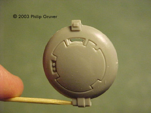
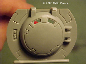
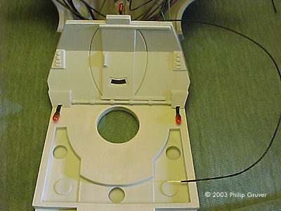
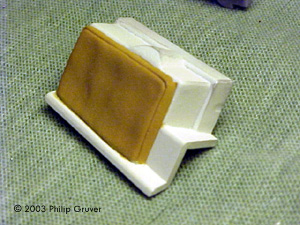
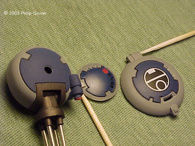
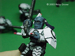
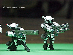
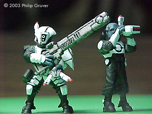
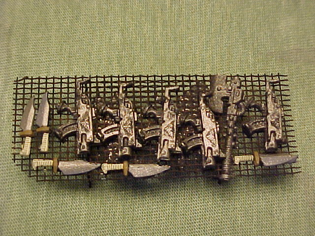
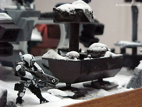
Image: Interior painting scheme. Image: Sampling of parts and subassemblies painted with a 50/50 mixture of Exhaust Metalizer and Burnt Iron and detailed with chrome silver and red. Image: Field Commander Image: Pilot/lookout atop Devilfish. Image: Warrior standing guard next to captured robot sentry with lighted Devilfish cabin in background |
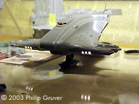
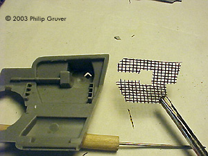
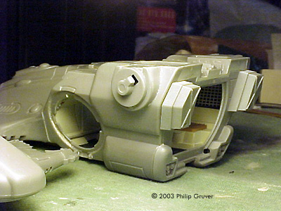
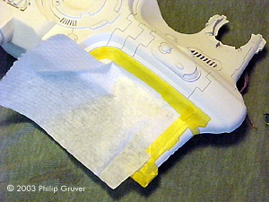
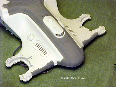
Vehicle Subassemblies I started by building up the vehicles into separate easily painted subassemblies consisting of the engine assemblies, rail gun, and vehicle body. All other individual parts were painted separately prior to final vehicle assembly. The really cool-looking pulse cannon that also came with the Hammerhead was relegated to the greebly box for a future (Star Trek?) effort. Sprue joints were sanded off individual parts using 400 grit sanding film. The engines and rail gun were glued together with Model Master Liquid Cement (in the black triangular bottle. In most cases the seams were small and I used enough cement that excess would squeeze out the seams. I then waited a day for the cement to dry before sanding. Once the bonds had cured, I would then file or sand using a course grit (150) sand film wrapped around an eraser to work off most of the material. As I got very closer to the seam I would then switch to medium (280), then extra fine (400), then ultra fine (600) sanding film till I got a smooth finish. I would then use a cotton rag cut from an old T-shirt to buff the surface. I recommend the sanding-film-wrapped-around-the-rubber-eraser technique as it applies a firm yet pliable force against round as well as flat surfaces. Where you come up against a corner, wrap the sanding film around the sharp edge of one of those slanted eras! Rusted old windscreen material was used to fill in the recessed areas in the cabin ceiling, 4, and sidewalls, 5. The intent of these was to create the illusion of handholds and also to obscure the lack of detail on the sidewalls around the engine mounts. The Hammerhead Vehicle is to be displayed in the flight configuration mounted on a brass post. To accommodate electrical wiring from the cockpit, the post is mounted through a hole cut in the access panel just aft of the front landing gear and into a plastic insert reinforced with plastic sprue. The Devilfish Vehicle is displayed in the landed configuration. Electrical wiring is routed through a tunnel drilled in the front landing gear. Hand drills, Xacto blades, files and sand paper were used to cut out the windshields which were then filled in with plastic shapes cut from a milk jug. Although this came out good, next time I will try Envirotex to create all the vehicle windows. Bulkhead and hatch view ports were also cut out, but these were left open. Vehicle Lighting These vehicles scream for lighting. The box cover paintings show bright yellow headlights and red cockpit and cabin lights. The head light ports in the fairing were cut out and filed down. 1.7mm, 1.5V rice grain bulbs were adhered in place with 3M transfer adhesive. Grooves in the chassis were also cut to make room for the bulbs. Three 2.4mm, 1.5V rice grain bulbs painted with Tamiya Clear Acrylic Red were used to light up the cabin and cockpit. All bulbs were wired in parallel to a single pair of lead wires that exit through the bottom of the vehicle. The lighting effect is subtle. The total resistance of both vehicles wired in parallel was 0.8ohms. Vehicle Interior Painting The vehicle body interior surfaces were painted prior to assembly. Unless otherwise indicated, an airbrush was used for all painting. A friend recommended interior buff similar to what was used for German tanks. The buff was actually a mixture of Model Master enamel flat white (90%) and flat brown. This was applied to the interior sidewalls, grills, ceiling, turrets, back wall and forward bulkhead. For the floors I used a dark gray mixture of Model Master flat black (90%) and white. Model Master flat black was applied to recessed areas in the ceiling and sidewalls. The grills were then pressed into these recessed areas. I liberally drybrushed the floor and buff surfaces with Testor's silver to give them a weathered look. For the bench seats I used flat tan that was then dry brushed with a slightly lighter shade. Vehicle Body Assembly With the interior completed, each vehicle body could now be assembled. The bulkhead was glued into the fairing with Model Master Liquid Cement. Next, the sidewalls were glued to he fairing. With the benches glued to the chassis, the chassis was then glued to the sidewalls, bulkhead and fairing. Finally, the aft wall was glued to the fairing, sidewalls and chassis. In most cases the seams were small and I used enough cement that excess would squeeze out the seams. I then waited a day for the cement to dry before sanding. With real small yet apparent gaps, I would brush Mr Surfacer 1000 along the gap and let sit overnight. With slightly larger gaps, I would use a toothpick to dab on a putty made by mixing Model Master Liquid Cement and ground up sprue (you mix this stuff the day before and let it become molten overnight) and let it set overnight. As with the engines and rail gun, once the bonds had cured, I would then file or sand using a course grit sand film wrapped around an eraser to work off most of the material. As I got very closer to the seam I would then switch to medium, then extra fine, then ultra fine sanding film till I got a smooth finish, and then a cotton rag for buffing. The process was repeated until most gaps were gone. The seam-sealing process is the most time-consuming, aggravating yet ultimately rewarding when the seam eventually disappears under a coat of paint. I'm still in a learning phase and only about 75% happy with the job I did. Vehicle Exterior Painting The external painting pattern is nearly identical to that used by Bill Morales. But where his coloring was based on shades of desert sand, my white/gray/blue coloring was appropriate for an urban winter setting. The white paint was Model Master Flat White. The gray was mixture of white (60%) and Model Master Flat Black. The dark blue was actually a mixture of flat black (20%) and Testors Flat Blue. I started by painting most parts and subassemblies with the flat white to act as a primer. After letting the paint cure for a day I then masked with Tamiya masking tape and paper towel to paint in the gray areas. After another day I then remasked and painted the flat blue. A Sakura Products Micron 005 black pen was used to fill in the grooves.I used a 50/50 mixture of Model Master Exhaust and Burnt Iron Metalizer on the engines (intakes and exhaust), drone undercarriages and guns and missile packs, body avionics bays and drone latching mechanisms, rail gun, and forward gun swivel turret. Testors Chrome Silver was hand-painted on the rotating gun barrels, drone guns, forward turret optics and landing gear struts. A Micron 005 red pen used for the missile caps, drone optics, upper turret optics and forward turret optics. Before applying decals to the vehicle body, engines and hatches, the surfaces were airbrushed with two to three coats (roughly two hours apart) of Future acrylic Premium Floor Finish (straight out of the bottle). The intent is to take the flat surface to a smooth glass-like finish necessary for the transparencies to disappear into. Testors decal setting solution was then brushed onto the surface and the decals were applied. Additional coats of Future were applied to make the decal borders virtually disappear. The next day the glossy areas were then airbrushed with two light coats of Polly Scale Acrylic Flat Finish (roughly four hours apart) cut with denatured alcohol (25%). With all surface preparation on the vehicles complete, final assembly began. All landing gears were glued in place with liquid cement. In the case of the Devilfish, the electrical wiring was laced through the tunnel cut in the strut before gluing. Antenna spines and undercarriages were glued to the drone head units. Missile packs were snapped into the undercarriage while the pulse rifles were glued to their undercarriages. 3M transfer adhesive was used to assemble for forward turret and to bond them to the vehicle bodies. This was done for easy removal should I later decide to change vehicle configurations. Similarly, the cruise missiles and all antenna spine where attached with transfer adhesive to the Hammerhead. Unfortunately, the forward-heavy railgun had to be glued to the turret. In hindsight I could have installed counterweights to balance the gun around the gimbal. Transfer adhesive was also used to assemble the Hammerhead upper turret and bond it to the vehicle body. The smaller turret was bonded with transfer adhesive to the Devilfish body. The engines were put onto the engine fittings. All hatches were attached with transfer adhesive in the open position for the Devilfish and in the closed position for the Hammerhead. The drones were dropped into their vehicle carriages and needed no bonding. Final vehicle assembly was then completed. Fire Warrior Assembly, Priming and Painting I selected six fire warriors in various poses holding different weapons and tools to be patrolling around the diorama in addition to the pilot/lookout sitting atop the Devilfish. All seven figures were primed with Citadel Black Primer (spray) and hand painted with Citadel flat acrylics. The helmets, gloves and armor and backpacks were painted white. The cloth undergarments and boots were left black. The weapons and backpacks were painted with a 70/30 mixture of boltgun metal and chaos black with highlights done with enamel silver. Skin was painted shadow gray. Hair was painted deep blue and the hair band was painted enamel silver. Weapon scopes, antenna and sensor tips were painted red. Captured Weapons and Greebly Assembly and Painting I used more window screen material to construct a table on which various captured weapons would be displayed. The weapons were epoxied down to the table and the entire assembly primed with Citadel Black Primer. The weapons were painted with various Citadel and Game Color acrylic paints including bonewhite, brown, shadow gray and bolt gun metal. The table was left black. From a box of old model parts I put to use a Space Shuttle Cargo Bay pallet, an old tank turret mounted on a piece of styrene tubing, and a pair of 1976-vintage Space 1999 Eagle landing gear. The entire assembly was painted with Model Master Burnt Iron with Exhaust Metalizer highlights. |
|
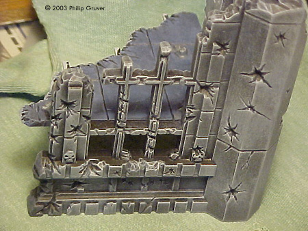
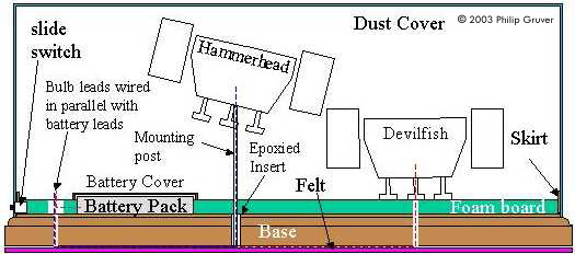
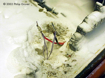
Building Structure Assembly and Painting Four building corner structures came in one package made by Citadel. I decided to use Insta-Cure super-thin cyanoacrylate to bond these pieces together. The outer wall seams went together very well and required minimal sanding. I dabbed on molten putty on the inner wall seams, let sit overnight, and then sanded them down the next day. I then glued the floor pieces into place also using super glue. After looking at hundreds of pictures of gothic-like structures on the internet and in books I settled on a painting scheme typical of what is posted on a gaming terrain site called Terragenesis.com. I first primed all pieces with Citadel Black Primer and then let sit overnight. The next day I gave the walls a modest dry brush using a number 8 brush (~1/2 inch wide) with a 50/50 mixture of Model Master Acrylic flat black and white. The next day I lightly dry brushed with a mixture of 25/75 black/white. The final drybrushing to highlight the edges was done with 90/10 white/black. The floor was drybrushed with a bluish Citadel shadow gray and then highlighted with the 90/10 white/black mixture used for the walls. In addition to the structure I wanted to have additional remnants of the building structure. I used ProForm Professional Formula All Purpose joint compound (yes, the stuff you repair walls with) to construct additional floor tiles. I spread the material out on a sheet of cling wrap stretched over a smooth counter top at the corners with tape. I let material dry for a couple of days and then cut grooves making ¾" squares. Although breaking the tiles into about 100 pieces was ultimately the intent, this happened anyway when I tried to pull the vacuum-bonded cling wrap off the counter top. Next time I do this if I don't want this to happen I will use wax paper which I will slide off the counter top. I then laid the delicate but solid tiles on a sheet of newspaper and primed both sides with Citadel black primer. The next day I dry brushed with Shadow gray and 90/10 white/black. Power Supply and Switch Construction A 1.5V power supply was constructed by taking four AA battery packs purchased at RadioShack and wiring them in parallel and soldered to a single set of lead wires. A slide switch was then spliced and soldered into one of the lead wires. I decided to go with four batteries because I didn't want to have to worry about changing the batteries for several operating hours. Since the total resistance of the lighting circuit was measured to be 0.8ohms, at and operating voltage of 1.5V the lights would draw (1.5V/0.8ohm)^0.5=1.3Amps. Conservatively assuming a total capacity of 4*1200mAh or 4.8Ah, the batteries should last about 4.8/1.3=3� hours. Diorama Construction. As with most of my supply purchases, the 14" by 11" Walnut Hollow Basewood base was purchased at D&J Hobbies in San Jose. On top of this a 3M transfer adhesive was used to bond a �" thick sheet of foam board cut just slightly smaller than the area of the top surface of the wooden base. A hole was cut into one corner of the foam board and the battery pack was epoxied into place. A ¼" tall five-sided cover was constructed from white cardboard stock to prevent joint compound from seeping into the battery pack. The top of the cover was painted earth brown and tile pieces and dirt were glued to the cover. A hole was cut into the adjacent edge of the foam board and the slide switch secured in place with two-part epoxy putty. 1/16th" thick Midwest Basewood was then cut into �" wide strips and used to make a skirt to close out around the perimeter of the foam board. The wood strips were glued to the foam board with Elmer's glue. A hole was cut in one of the strips for the slide switch. The wood base and skirt were then stained with Minwax Antique Maple Gel Stain and gloss coated with Flecto Varathane Professional Clear Finish 900 Gloss. After curing, these surfaces were then masked with masking tape to prevent subsequent damage during the buildup of the diorama surface. Holes were then drilled through the foam core and wood base. One small hole is for the Devilfish wiring. Through a larger hole a section of 5/32" diameter, 1" long brass tube was then epoxied into the hole and allowed to cure overnight. The post used to hold the Hammerhead in the flight position would eventually be inserted into this larger hole. A third hole was drilled adjacent to the battery pack and more of the foam core around this hole was hollowed out to contain the soldered wires. The plan is to eventually route the wires from the vehicles, through the holes, along the bottom of the base, and up through the hole to the battery packs. All holes were temporarily plugged until final assembly. The building structures were bonded to the foam board using 3M transfer adhesive. A ~1/8th inch thick layer of joint compound was used to cover the foam board. Additional joint compound was used to create raised areas. While the joint compound was still wet, tiles were pressed into the joint compound along with bits of dirt and rock to provide texture. The fire warriors were mounted at various locations on the diorama mounted with Elmer's glue or joint compound. The two spare drones were mounted by drilling a hole into their undercarriages and inserting a 2" length of 1/32" diameter Plastruc rod. For one drone, the other end of the rod was inserted into a hole drilled into the top of a building arch. The other drone was mounted into the joint compound. Elmer's glue was used to mount the captured weapons table onto the tiles at one end of the diorama and the robot gun sentry to the battery pack cover tiles. Felt padding was adhered to the bottom of the base with transfer adhesive. A slit in the middle of the felt along the center of the base allows for eventual access to, and routing of, wires along the bottom of the base between the battery pack and vehicles. Final Assembly - "It's Snowing!..." Snow was added using a really neat technique I read about using water-thinned Elmer's glue, an airbrush and baking soda. The airbrush is used to control the application of Elmer's glue. The glue is allowed to set for a few minutes and then the baking soda is then sprinkled in place. Additional loose baking soda is then sprinkled as needed. To give a freshly fallen snow look, gentle dry airbrushing from about 15" away smooths out the clumps and make it look windswept. I highly recommend trying this first before using on a real diorama as it takes practice. If the glue is too wet the soda will foam or cake up. If it is too dry it won't stick. Be sure to clean your airbrush out with warm water immediately after using so as to prevent the glue from setting up. Snow was allowed to buildup on the building structures and on the robot gun sentry but was brushed off the weapons tables, fire warriors and drones. Foot steps between the warriors and the vehicles were impressed into the snow using toothpicks. With a pristine covering of snow, the vehicles were then mounted into position routing the wires through the holes. The wires were then brought up back through the third hole and soldered to the battery pack lead wires. The wires were sealed with electrical tape and buried in the hole. This hole was then filled in with tissue paper and covered up with loose baking soda. I'm pleased with how the snow looks. I actually felt cold looking at it! Finally, a 9" tall five-sided display case cover constructed from 1/8" thick clear acrylic was purchased from Acrylonics in San Jose, California to protect the finished product. The diorama was completed in time for entry into the Japan Collectibles 2003 Year-End Model contest. Mistakes and Lessons-Learned The list is quite long so I'll just cover the most important:
|
![]()
This page copyright © 2003 Starship Modeler™. First posted on 17 December 2003.
![[Click to enlarge]](pg_tau/pg_tau_fig03.jpg)
![[Click to enlarge]](pg_tau/pg_tau_fig13.jpg)
![[Click to enlarge]](pg_tau/pg_tau_fig26.jpg)
![[Click to enlarge]](pg_tau/pg_tau_fig29.jpg)
![[Click to enlarge]](pg_tau/pg_tau_fig39.jpg)
![[Click to enlarge]](pg_tau/pg_tau_fig42.jpg)
![[Click to enlarge]](pg_tau/pg_tau_fig43.jpg)