
|
By James Bryson - images & text © 2003
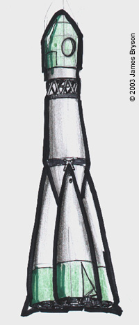
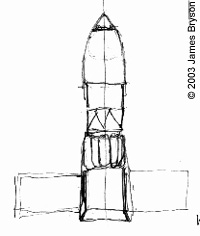
Around February or March of 2001 I was approached about the possibility of constructing a miniature Soviet-style rocket for a low-budget music-video. Director Sera Prince had seen a documentary on the Soviet space program, and was seeking to emulate the look of their technology in her video for a John Stanford track called 'Sea of Tranquillity'. The first information I was given was that absolute accuracy was not necessary, just that the rocket should look 'Russian'. Sera wanted to show the launch, so I assumed that the rocket would need an intricate gantry model. A space capsule, to be shown in orbit, was also required, and this I planned to execute at a larger scale. Conception I did two quick sketches to present at the first production meeting. My initial thoughts on the rocket were to go for the proportions of the Vostok launch vehicle rather than the Soyuz (which always looks a little top-heavy to me), to widen the horizontal proportions by about twenty percent to make the rocket look a bit more squat and powerful, and, just to be different, reduce the number of strap-on boosters from four to three. I also took along a basic maquette, taped together from some parts of the 1/144 Aer Moldova Vostok. |
![[Booster configuration]](jb_rocket_15.JPG) |
|
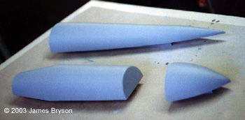
Image: Booster and capsule "tools"
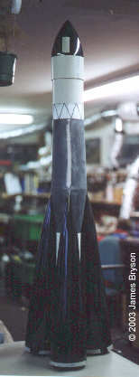
Image: Main assemblies mocked-up
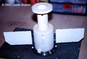
Image: Rear of capsule, without tanks |
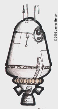
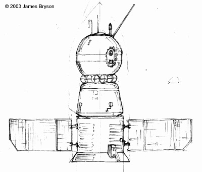
My sketch for the capsule was based on a little russian ‘space-pod’ model, which fellow model-maker Alan Pilkington had built for a laugh using a plastic cup! I incorporated an inset side-opening hatch and a ring of spherical tanks, which always looks very ‘Russian’. My thoughts on the rocket were well received, however my capsule concept was vetoed as appearing as too small a craft. The theme of the video was to be loneliness, and the music has a very subdued tone to it. Sera envisioned her cosmonaut setting off on a solo mission, perhaps to some near-earth asteroid, for about two months. She had in mind a longer multi-section craft, more in keeping with a Soyuz capsule. With this new information and a materials budget of $300, my plans could become a little more concrete. My initial estimate of the rockets’ size was based on using 3in and 4in (75 and 100mm) diameter Plastruct tube, which is relatively expensive. In the interests of economy, I investigated the available sizes of PVC plumbing pipe. I found I could buy the requisite lengths of 82mm and 110mm diameter pipe for only $9.00 NZ, roughly $4.00 US, not only saving a small fortune, but adding considerably to the strength of the model. Based on these diameters, I drew up an outline plan for the rocket. Scaling up the vertical measurements of the1/144 kit four and a half times, the final height came out at a surprisingly tall 1140mm, or around 45 inches. The horizontal measurements were increased five and a half times, which set the scale of the model at around 1/24. My next meeting with Sera saw my second attempt at a capsule design rejected, again for being too short. On the real Vostok, and in my design for the rocket, the nose-cone containing the capsule is separated from the launch vehicle by a web-work truss. This gives the nosecone a discrete proportion, which I was reluctant to break out of, in the interests of on-screen credibility. Sera, however, was not aware that the nosecone was an ejectable cover, and had thought that this was the part that actually entered orbit. I suggested that it would be easy to accommodate this, by making the nose-cone and web-work truss merely the upper half of the capsule, and making a new half-model to join on below this, as if the shell of the launch-vehicle has opened to reveal it. I also suggested making the top of the nose-cone ‘wild’ (removable), to reveal a docking hatch. The capsule would then lose the bullet shape of the rocket and look more distinctive, and would also accommodate a mounting point for photography. Also dropped during this discussion were the gantry, which Sera deemed un-necessary, and any engine detail on the bottom of the boosters, as the storyboarded shots never saw this area. All of a sudden, instead of the three models I had thought were needed, I was building only one and a half, and with time already beginning to crunch, I was more than happy to revise my ideas. Construction The rocket divided up into six sections: nosecone, truss, fuselage or main booster, and the three strap-on boosters. Beginning actual construction, the 82mm pipe was cut to length, and two rings of 18mm MDF epoxied in place, at the top and part way down, to support the conical sections of the main booster. I first attempted to form one of these sections by bending and gluing a fan-shaped piece of styrene in place, but the result was less than pleasing, and seemed very weak. Very quickly, this section of the model joined the list of pieces I would make a solid tool for, and have vacuum-formed. Initially, I had thought this would only be necessary for the 2D curves of the nose-cone and boosters. Tool, in this case, refers to a shape made slightly smaller than the final part, to allow for the thickness of plastic. All of the final pieces are circular in cross-section, so I would need only to make half of each shape, with two vac-forms making up each final part. From my plan, I made plastic templates for one side of the elevations of the nosecone and boosters, subtracting 2mm from the edges, as I planned to use 2mm styrene, and adding 12mm to the bottom for safety. I cut an elevation of each part from 6mm MDF. The conical section, with its straight sides, did not call for a template, so was just drawn out on the wood, with a 12mm margin both top and bottom. The booster and nosecone tools had half-elevations added in 3mm MDF on their centre lines. Semi-circular profiles were added to the booster and conical pieces in 3mm. The safety margins were taken up by similar profiles in 12mm MDF. The plan now was to surface these skeletal shapes with polyester car filler. Each cavity was filled with a section of urethane insulation foam (styrene-based foam would be attacked slightly by the filler as it cured), up to about 5mm from the surface. I could now have slathered an excessive coating of filler onto the tools, and laboriously sanded down to my final shapes, however here I am again indebted to Alan Pilkington. Alan was making a large model of his own, and gave me the benefit of his experience in forming the 2D curves from filler. Although it is quite a process, it is still much less work, and more reliably accurate, than sanding down to size. The key is a negative, or female, template, matching the profile of the side elevation. This is scraped over the wet filler, ensuring that no excess is left to be sanded away. At first, the result is horrifically rough and uneven, as the wet filler pulls at itself rather than laying smooth. The answer is successive coats, added after the previous coat has hardened. Each coat produces a smoother result, as you fill successively shallower gaps up to the surface. I needed such templates only for the nosecone, and the top section of the strap-on booster. They were made in 3mm MDF, with the working edge cut down to a thin blade. Because the nosecone and booster come to a point, I found it desirable to drill a small hole in the apex of the tools, and to add a brass pin to the corresponding point on the templates, which would hold it on the centre of rotation. The 1D curves on the conical section were scraped with a straight piece of wood, while the lower three sections of the booster tool, which have a very slight 2D curve, were done with a metal ruler which could be held to that curve. After four or five coats and some spot filling, a light sand with 400 grade paper left each piece ready for painting. Two or three coats of high-build spray filler then followed, sanding in between. The deadline was very much on my mind, and I settled for a ‘good enough’ finish, rather than waste time trying to get it perfect. The pieces were put aside until I could organise the actual vacuum-forming, and I spent a couple of days on the cylindrical parts of the nose cone and the rear half of the capsule. For the lower part of the nose-cone, beneath the piece to be vac-formed, I used two pieces cut from 110mm diameter tube. I cut a thin vertical section from one piece, so, when held closed, it would nest within the other section. With the 3mm wall thickness, this gave me a cylinder which stepped down from 110mm to 104mm. Circular MDF bulkheads were cut for each end, with 1in holes to accept the piece of dowel I would use as a model-mount. |
|
The capsule rear was constructed from MDF bulkheads and sections of 110mm and 55mm PVC tube. The 55mm section would be covered by a double ring of fuel/oxygen tanks. Atop this was a ring of 12mm MDF, with its edge slightly angled to match the top of the conical section on the fuselage, where I had added a similar ring to the 82mm diameter pipe. Both pieces would end up 104mm wide, matching the bottom of the nosecone, and the still-on-the-drawing-board truss. I wanted to add a Soyuz-like conical flange to the rear of the capsule, and had planned to form this from flat plastic. My earlier failure with this technique led me to make a vac-forming tool for this part as well. This was cut from 18mm MDF, after first setting the bandsaw to a 40 degree angle. A 5mm lip was added in 3mm MDF, only after which I realised this could just as easily have been cut from the excess plastic after vac-forming. Doh! The Wellington yellow pages revealed only half a dozen businesses equipped for vacuum-forming, and I rang them all. The most surprising response I received was that what I wanted to do was not vac-forming at all! Vac-forming, I was told, is done into a cavity, or female mould. My tools would have to be re-moulded, at a cost of over $200 each! Thanks, but no thanks... Fortunately, one firm referred me to a plastics manufacturer which hadn’t even listed vac-forming in its’ ad, and it was only a few minutes travel from my workshop. They agreed to form the eleven pieces I’d need for $200, materials and labour included. Although this was a major whack out of my budget, results were more or less guaranteed. I dropped off the tools, and picked up the vac-forms the following day. After whipping off the flange from each piece on the bandsaw, I made a scribing tool to remove the 6mm of extra height left by the MDF profiles. It’s desirable to have some excess in a tool, as even the strongest vac-former will still leave a meniscus, or slight curvature, on the edge of the part. The scribe was simply a small block of MDF with a hole drilled at 6mm high, into which I pushed the point of a compass. It was a simple job to scribe around each part when held flat on the workbench, deepen the scribe lines with a scalpel, and then snap off the strip of plastic. The two halves of the conical section were epoxied to the tube-and-MDF fuselage made earlier. The halves of the nosecone and boosters benefited from having small locating tabs added in plastic sheet. Before the booster halves were joined I plotted and drilled the placement of two screws per booster onto the fuselage, and cut corresponding keyhole slots into the boosters. Detailing At this point, using a piece of 50mm polystyrene foam as a stand-in for the truss, I was able to mock up the entire model. This was a valuable morale booster as I headed into the last week of my schedule. I was still working a day job at the time, and all work on the rocket was done after hours, so I was now facing several late nights in the workshop to complete the project for the shoot on the coming weekend. Concentrating on the nosecone, the two vac-forms were glued together, then sawn through about 35mm from the top. After some slight sanding down, a disc of sheet plastic was superglued onto each part at the join, to make up the thickness of lost material. The pieces were rejoined with double-sided tape and sanded to shape as one unit. The docking hatch started as a spare casting of a piece from another spaceship. A 1in hole was bored into it, and a heat-formed styrene dome, the actual hatch, detailed up and tacked into place with superglue, making it easily removable. The vac-form was then glued to the cylindrical section. I detailed the step where the cylinder changes diameter with those little triangular bits that come with a DS9 fibre optic lighting kit. Following a visit to the garage in suburban Wellington where the live-action capsule interior was being built, I made up a 1/24th scale window from kit-parts to match it’s full-size counterpart. This push-fitted into the side of the nosecone section, and contained a 12v bulb, wired up to a two position switch on the other side of the model. By now my schedule had forced me to abandon the time-consuming truss, which I had planned to silver-solder together from brass rod and tube. I had to concentrate instead on the rear half of the capsule, adding the vac-formed flange, and solar panels made simply from welding rod struts and Evergreen tiled sheet styrene. The five rear thrusters were cut into a shallow plastic dome (from a cheap battery powered camping-light), which was glued in place, the middle thruster doubling as a mounting point. Detail came mostly from Revell’s re-issued Nike Hercules missile. I made patterns for the two sizes of fuel/oxygen tank from Plastruct hemispheres and kitparts, and poured two silicon moulds of each, which, as I needed twenty-four tanks altogether, made the casting process much quicker. Before supergluing the smaller tanks in place, I drilled four mounting holes around the 55mm PVC to accept a half-inch support rod, a piece of which I fitted into one end of the 1in dowel. It would be an easy task on set to snap off a tank covering a hole, and just as easy to glue it back on again. The deadline loomed, and unfortunately I had to call it quits on any further detailing. With the model due on set on Saturday after lunch, I had just two nights and Saturday morning to paint the thing! The model was rubbed down with denatured alcohol and primed grey, after first warming the spray-cans in warm water (it was the middle of winter, past mid-night in an un-heated workshop. There's no business like show business...). For the top-coat, I’d had two spray-cans of matt automotive lacquer specially made up. The overall colour is an off-white ivory, while for the nosecone and the bottom of the boosters, which were a heat ablating green material on the Vostok vehicles, Sera and I chose orange. We had noticed a certain orange-brown colour on some of the Soviet hardware in our reference, and, as the launch in the video is set at night, felt this would be preferable, and would also matte better against a green-screen. Strangely enough, with my being a long time Gerry Anderson fan, it was only after the shoot that I realised my three-engined orange rocket looked a little familiar... The six separate sections were top-coated in ivory one evening and left to cure, with the orange sections masked up and sprayed the following evening (Friday night), along with some sections picked out in a dark silver-grey. Filming Saturday morning was mainly taken up with cutting a mask for the red star and the Cyrillic lettering. I had planned to have vinyl lettering cut for the model, but my usual supplier had gotten out of the business, and I didn’t have time to hunt around. Instead, I mocked up what I wanted in photoshop and printed it out at the right size, then stuck it to double-sided tape and cut around it to produce my mask. The word is ‘zvezda’, Russian for ‘star’. The last thing I had time to do was add the many panel lines in pencil all over the model, before packing model, tools, and materials into the car and getting across town to the set, actually the basement garage of a post-production facility. The missing truss section was a small problem in that it would have been screwed in place, and securely joined the model. For the shoot, the nosecone was held to the launcher, and subsequently the capsule section, with a high strength double-sided tape known in the film industry as ‘gorilla snot’. No, I’m not kidding... For shots of the complete rocket, the one-inch dowel mounting rod was screwed to the off-camera side of the fuselage so it projected out the bottom and could be held in a C-stand. The set-up was very simple and consisted of a few lights, the greenscreen, and a digital video camera on a small boom arm. While shooting was in progress on the rocket, I took the opportunity to spritz a bit of weathering onto the capsule rear and the docking hatch, and to put a blue wash over the solar panels, which were still in grey primer. |
|
Re-setting for the capsule shots was a matter of popping the tape join on the nose cone and attaching it to the capsule section, and similarly removing the top of the nosecone and replacing it with the docking hatch. Of the six mounting points on the capsule, we ended up needing only two, the rear and one of the middle ones. Better too many than too few.
Shooting lasted from 1 o’clock to around 6 that evening, at which point I packed out, went home, ordered pizza, and caught up on some sleep! Afterword My final costs for materials on the project were around $400 NZ, well over the $300 I was given, but one of my conditions, as on any project where I'm not paid for my time, was that I got to keep the models, so I didn’t begrudge making some contribution. Standard day-rental for such items or props is 10% of their total cost. The models represent about two weeks full-time work, and had I been on paid time the cost would have been more like $3000. Of course in that case the production would expect to keep the models. In this case they had a say in the design, had the models purpose-built for them, and got the footage they wanted, so we all ended up ahead. I still plan to finish the rocket to my own satisfaction at some point, so it can be displayed somewhere, hopefully leading to more use for it and more employment for me. There’s a lot more detail I’d like to add, it looks too short without the truss, and a rocket without engines... give me a break! |
|
![]()
This page copyright © 2002 Starship Modeler™. Last updated on 22 January 2003.

![[Capsule]](jb_rocket_18.JPG)
![[Click to enlarge]](jb_rocket_19.JPG)
![[Nose cone]](jb_rocket_08.JPG)
![[Basic pieces]](jb_rocket_10.JPG)
![[Basics built]](jb_rocket_12.JPG)
![[Capsule rough]](jb_rocket_17.JPG)