
|
By B.P. Taylor - images & text © 2004
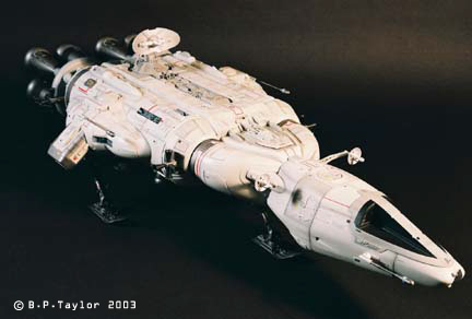
The 'Ranger' was built in my spare time over a period of about a year and four months and was my entry at the 2003 Wonderfest. At 1/24th scale, the model measures in at about 34" (864mm) in length and 17" (432mm) wide. Designed as a planetary survey vehicle, the model rests on a tri-gear arrangement. The front section is capable of separating from the rest of the vehicle, much like Sky 1 separates from the Diver section in the series 'UFO'. Held in place by upper and lower retaining clamps, this section could detach and operate independently, leaving the remainder in orbit to serve as a sensor platform and relay station. The forward gear is fixed to the lower clamp and swings away with it upon separation. |
![[Click to enlarge]](bt_ranger_27.jpg) ^ Completed 'Ranger', portside. |
|
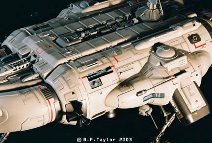
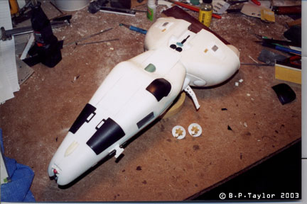
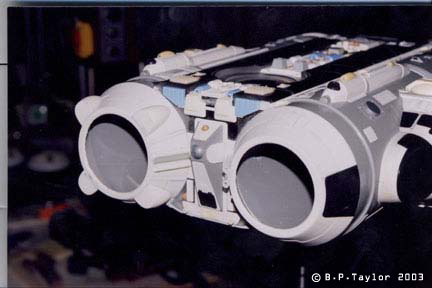
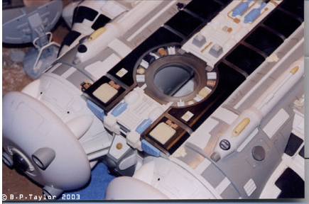
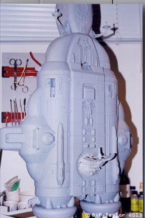
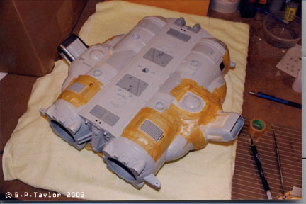
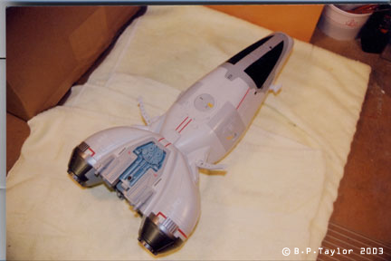
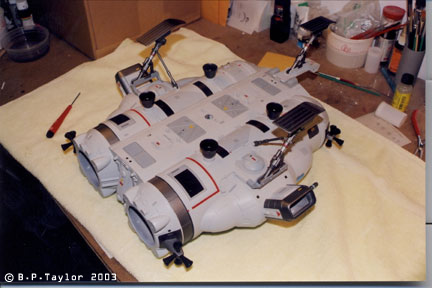
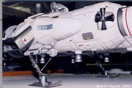
Image: Completed 'Ranger', starboard. Image: Close up of engines and rear deck. Image: Portside detail. The recessed area near center is a gear bay from a Stealth fighter kit. |
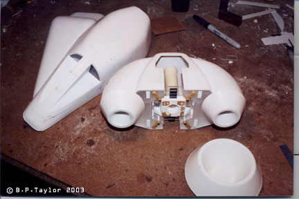
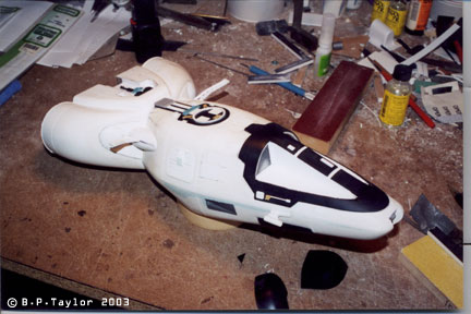
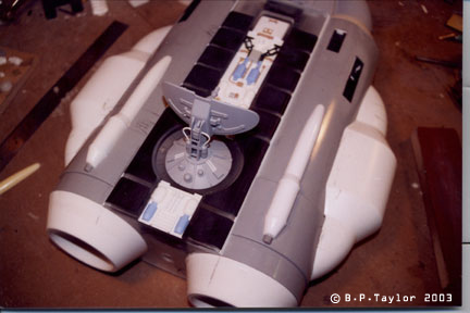
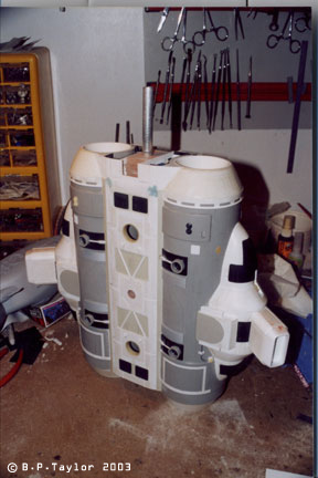
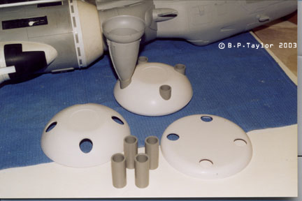
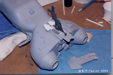
Except for a full-sized drawing establishing basic sizes and proportions, the model was completely improvised. Locations for the many scribed lines and various surface details were determined by drawing on the model lightly in pencil. Scribe lines were created with several flexible rules and templates using the back edge of an x-acto blade that was ground to a thin profile. A variety of materials and processes were used to create the ‘Ranger’. The model is constructed primarily of acrylic sheet, ABS, styrene and PVC. Landing gear supports were machined and soldered brass. Many of the major components were vacuformed, while others, such as the rear engine bells and landing gear, required the creation of masters and RTV molds into which urethane resin was cast. Some parts required a combination of techniques. The engine bells, for instance, required two patterns to be turned on the lathe – one for the primary bell and one for the ‘skirt’. Vacuform shells were produced of both of these and after assembling the two and adding a few details and scribed lines, a two piece mold was made from which the requisite 8 bells were cast. Incidentally, the engine arrangement that I arrived at was influenced by the Russian design philosophy of clustering engines. As it appeared at Wonderfest, the ‘Ranger’ displayed a pristine paint job simply because I ran out of time. I generally prefer subtle weathering on my models and have since applied a bit of pastel chalk to provide a little tonal variation to the surfaces. Despite the lack of weathering, the ‘Ranger’ received a Gold Award in the Vehicle/ Mech category in the contest. The quality of work on display at Wonderfest is truly inspiring and to have the ‘Ranger’ recognized with any award, considering the hundreds of amazing entries, is something I’m extremely proud of. Construction Image : I decided that it would be best to start with the front section. Patterns were hand-carved from scraps of clear pine and renshape, then vacuformed in .093 ABS sheet. Image : Various cut-outs and bulkheads were added to the vacuform shells and the cockpit area is taking shape. At the lower right is one of the vacuform pieces into which the engines of the front section will eventually fit.Image : The three vacuformed shells making up the front section were joined together and blended together with applications of bondo. Scribe lines have been cut in and detailing is well underway. The black ‘cowl’ around the cockpit area was derived from an additional .030 PVC vacuform shell pulled over both the pattern and the initial .093 shell. Carefully trimmed to shape, it was then glued in place with plastic solvent. Two other thin plates await attachment. Sensor booms were fabricated of sheet and strip styrene. Image : More contoured plating was added to the bottom of the front section. Small sensor dishes were vacuformed and detailed with modified tank wheels. Image : The basic construction on the main body of the ‘Ranger’ was of acrylic sheet and EMA tubing. Patterns for the ‘blisters’ were created and vacuformed in ABS sheet. The blister shells were then fitted and solvented into position, with bondo taking care of any minor gaps. The main sensor dish was a combination of vacuformed and kitbashed pieces and removal provides access to the internal cavity where LED circuit boards and batteries will reside. Image : Additional structures were fabricated and added to the large blisters while the bottom gets a little attention. Note interconnecting aluminum rod that serves to support the front section. Image : As described in the text, a pattern was made for the main engine bells while the combustion chambers began as renshape turnings which were then vacuformed in ABS. Inspiration for these came from a ‘pancake’ compressor. |
|
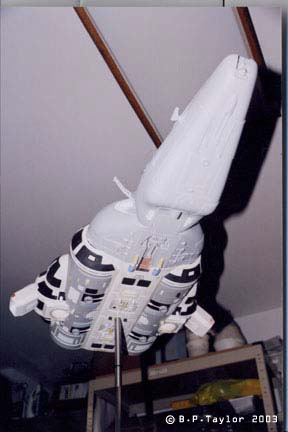
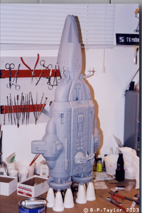
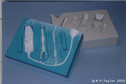
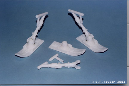
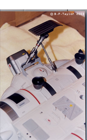
Image : The main engine bell was molded in RTV as a two piece block mold and cast in urethane resin. Image : Additional small blister shapes were cast up and applied to the rear of the main body to serve as screw bosses for attaching the combustion chambers and engine bell assemblies. Image : Styrene kit parts and urethane castings provided additional detailing. Image : Front section mated to the main body. At this point, about the only remaining components to be made are the retaining clamps, landing gear and the RCS assemblies. Image : (Before) This and the next image illustrate how a coat of primer pulls everything together and unifies what is essentially a collage of bits and pieces into a cohesive whole. It’s the time I look forward to the most in model making. It’s also the point at which you realize how much work remains before the model is actually ready for its base coat of paint. So out comes the tube of spot putty and the next thing you know, your model looks like it’s got a case of the measles. Image : (After) Image : Closer view of main body detailing Image : Landing gear supports were fabricated out of machined and soldered brass components. A jig was made to hold the pieces together so they would remain properly aligned while each joint was being soldered with a micro-torch. The strut master was built up of various diameters of styrene tubing and detailed with kit parts. Image : The lower clamp and strut assembly is test – fitted with the front section. Image : Footpad and landing gear components were bedded down in clay and parting lines carefully established in preparation for molding. Taking your time here will result in castings that require very little effort to clean up. Two different types of RTV rubber were used and account for the color differences in the mold halves. The steel pin visible in the strut is removed from each casting and a brass rod is inserted for rigidity. Image : Perfect parts, if I may say so myself. These castings of the landing gear components required only minimal clean-up, then were drilled out for pins to allow the foot pads to pivot. Image : I chose a light grey lacquer for the overall base coat, then began masking off various panels and areas with masking tape. These were sprayed with a couple of darker shades of the base color, as well as steel and black. Recesses were airbrushed a medium blue-grey. Image : With painting completed, custom-made graphics were applied, mostly in the form of call outs and bands of various widths. These were then sealed on with a satin clear coat. Image : The lifting jets, landing gear assemblies and RCS nozzles are all fixed in place with epoxy. The RCS nozzles had as their origin the tip of a pen. A two-piece RTV mold was made of this tip and the sixteen nozzles were cast in urethane resin. Image: Close up of landing gear assembly. Image : Belly up on the workbench, the combustion chambers are screwed on and the engine bells are inserted into the short lengths of EMA tubing at the ends of the chambers. Image : Using a stiff brush, dark grey pastel chalk is brushed along panel lines, in recesses and applied to form streaks all over the model. In keeping with my more subtle approach, I don’t over do it, preferring to use the pastels just to introduce a little tonal variation to the surfaces. This also gets sealed on with a satin clear coat. Image : Low angle view provides a good look at the landing gear assembly, lifting jets, RCS and LED spotlight. Note also the subtle pastel weathering. |
![]()
This page copyright © 2004 Starship Modeler™. First posted on 27 October 2004.
![[Click to enlarge]](bt_ranger_30.jpg)
![[Click to enlarge]](bt_ranger_31.jpg)
![[Click to enlarge]](bt_ranger_32.jpg)
![[Click to enlarge]](bt_ranger_33.jpg)