
|
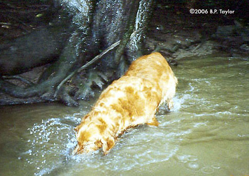
By B.P. Taylor - images & text © 2006 For the minority of us in the modeling community who enjoy scratch building futuristic vehicles and hardware of our own design, inspiration can come from virtually anywhere, and sometimes the best ideas can be found in your own backyard. The Skimmer , which is the subject of this article, was inspired by walks along the backyard creek with Zoie, our Golden Retriever. In one stagnant part of the creek, there are usually hundreds of water striders on the surface, which Zoie always enjoyed playing with. She seemed to have such a great time chasing the little buggers around, trying to bite at them as they would scatter in all directions. |
![[Please click to enlarge]](bp_skimmer/bp_skimmer_0028a.jpg) |
|
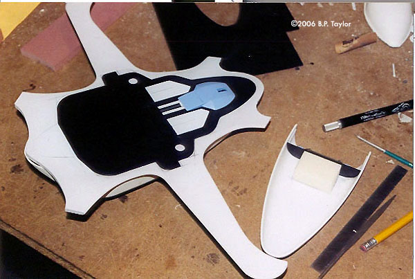
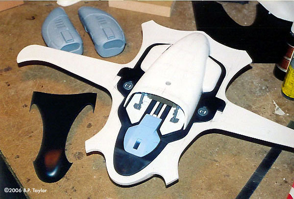
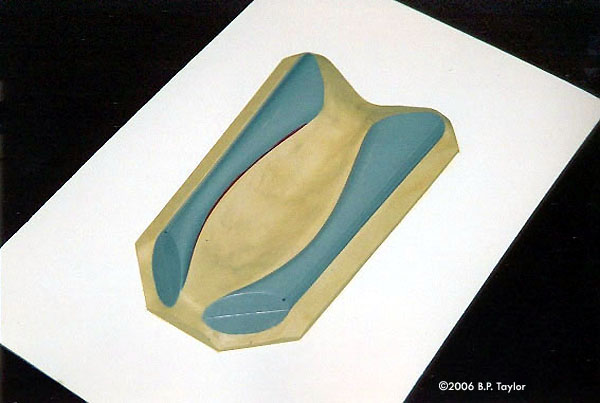
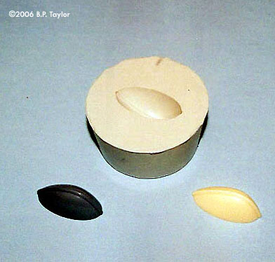
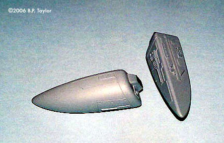
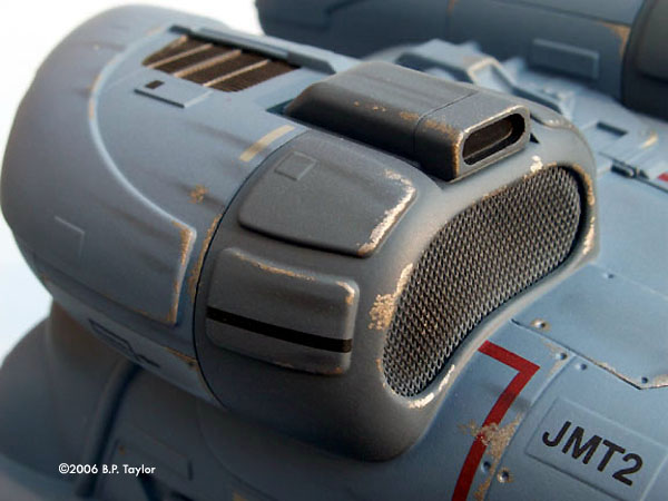
Image: The Skimmer was inspired by trips to the backyard creek where Zoie, our Golden Retriever, would chase water striders. Image: Recesses are added to the nearly completed engines. Bright LED panels were then mounted to these with epoxy, and reinforced with supporting ribs. Image: Completed engines with aluminum mesh intakes. Image: The secondary shells are carefully cut out and used to build up additional layers of detail. Image: Using the vacu-form shells, sheet plastic and kit parts, the underside takes shape. Image: More Image: More progress Image: Landing legs were molded in RTV and cast in urethane resin. Here the masters are bedded down in Klean Klay, the parting lines having been established with various sculpting tools in preparation for molding. Image: The ōfeetö were also urethane castings from an RTV mold.
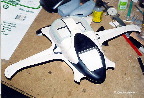
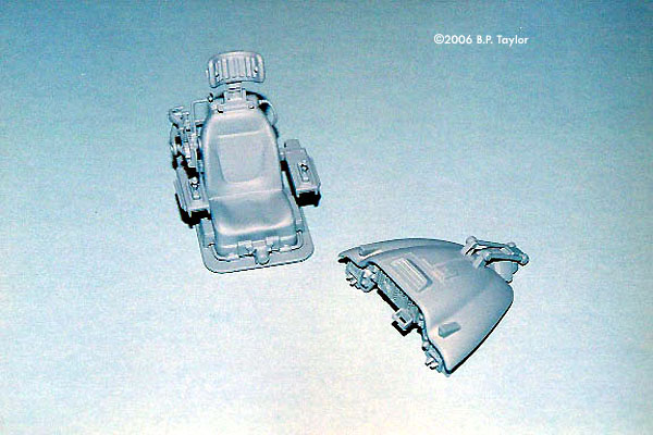
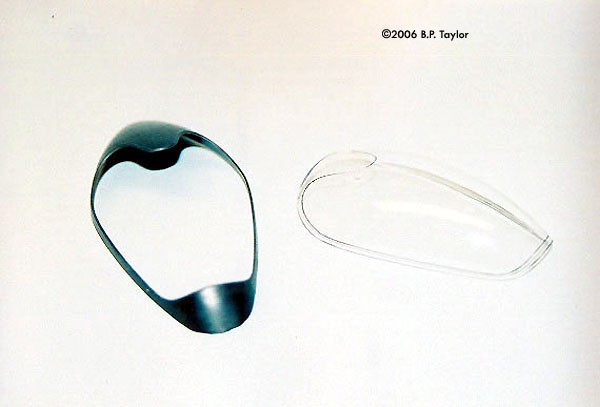
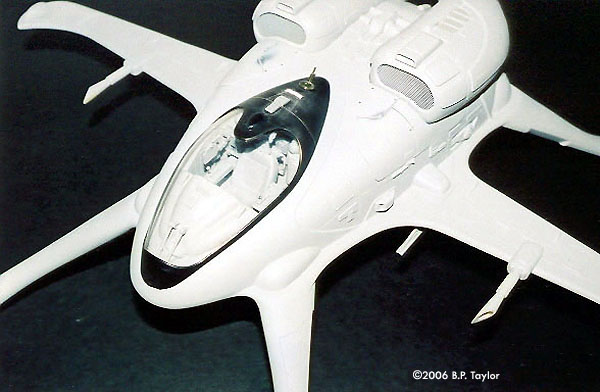
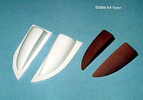
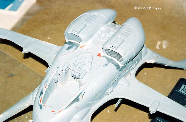
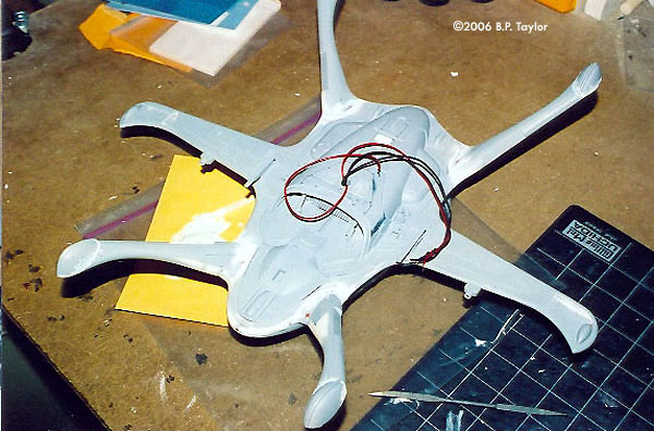
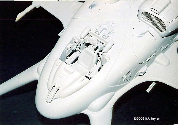
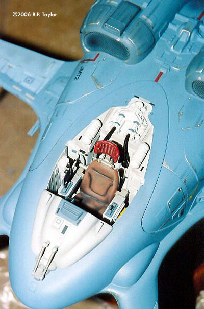
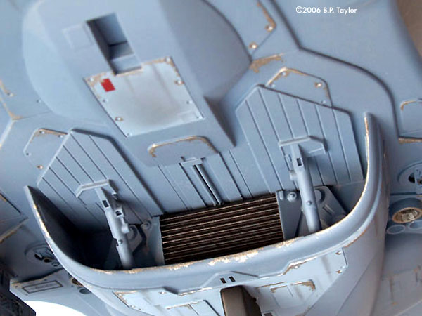
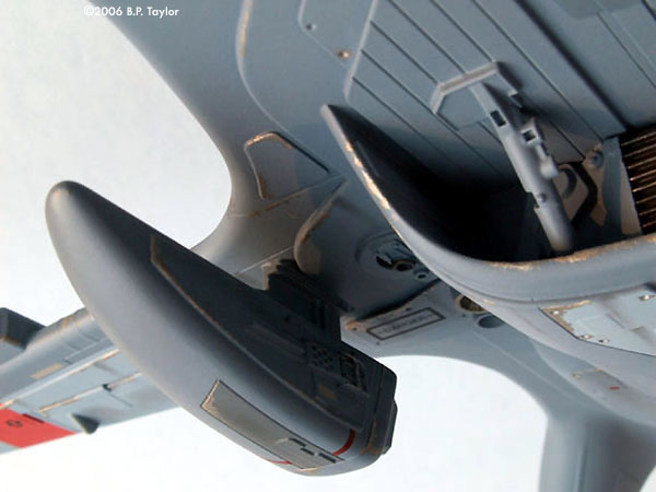
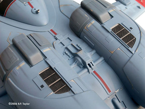
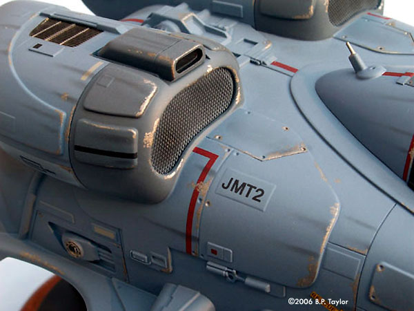
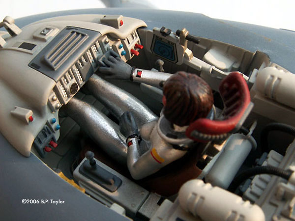
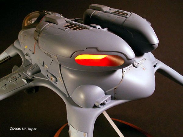
Image: Seat - before and after Image: Completed seat assembly and dashboard Image: Canopy bubble and surround after trimming Image: Completed canopy assembly is fitted to main body Image: These pieces were added beneath the wings to give the Skimmer a more aggressive look. Image: At left are the basic vacu-form shapes and at right, the carved Renshape patterns. Image: Engines are glued in place, final applications of Nitro-Stan taking care of any minor trouble spots Image: Belly-up on the workbench, the wires for the engine lights will be routed through a groove milled into the acrylic display stand Image: Bottom view of Skimmer Image: Close-up of interior details in primer Image: Another view of the same area after painting and detailing Image: Final details are painted on with various acrylics and Model Masters steel to simulate paint chipping Image: Skimmer from above Image: Close-up of dashboard Image: Lower intake detail. Image: Another view of underside details Image: Starboard wing and blaster Image: Engine details Image: Close-up of starboard engine intake area Image: Port side details adjacent to canopy Image: Close-up of Skimmer engine. Note panels built up from secondary vacu-form shells Image: Looking into cockpit interior and pilot derived from Preiser 1/24th scale female figure kit Image: Another shot of interior and pilot. (Yes guys, they're real!) Image: Engines are illuminated with LED panels obtained from All Electronics |
After one particular trip to the creek, I made a single little pencil drawing of a vehicle based on the water strider that, with very little alteration, became the basis for the Skimmer . I simply took this one crude top view drawing, enlarged it several times on the copier until it was what I guessed to be 1/24th scale then cleaned up all the lines with various straight edges, radius guides, and circle templates, before running off multiple copies to work from. This would be enough to get me started, as I usually like to make things up as I go, relying on my improvisational model making skills - and anyway, it's a lot more fun to just wing it! Getting Started After first coming up with a plan of attack, I made a list of the vacuum form patterns I would need to make. For the most part, the various patterns were created from urethane foam and renshape. The model was then assembled from the resultant vacuum form shells onto a flat wing plate and detailed with additional layers of vacuum formed PVC, styrene sheet and strip, resin castings and a few kit parts, as well as a fair amount of panel scribing. Beginning with the wing plate, I took a copy of my drawing and lightly spray-mounted it to a sheet of ABS. I then carefully cut this out on the bandsaw as close to my lines as possible. Final shaping on this plate was done with both spindle and disc sanders while the full radius on the wings was created with files and sandpaper, using a radius gauge to check my progress. With the wing plate done (upon which all else would be attached), I moved on to the vacuum form pattern for the main body of the Skimmer . From a chunk of ten-pound density urethane foam, I cut out the general shape with the bandsaw then using various rasps and coarse-grade sandpaper, arrived at the final form. Most of this was done by eye because of the shapes involved. In the same manner as the main body, I created the remaining vacuum form patterns, most of which can be seen in the accompanying images. Once I had the various vacuum form shells, I commenced to trimming them by repeatedly scribing around them with a height gauge, then snapping off the excess plastic with pliers. This trimmed edge was then sanded flat on a sanding board, large sheets of sandpaper that are stuck down to a piece of MDF with either spray mount or double sided tape. While vacuum forming the main body, underside intake, and engines, it made sense to also vacuum form secondary shells that would be used to create raised panels or cladding, as it is also called. The easiest method for producing this additional layer that conforms perfectly to whatever shapes you are creating, involves taking your trimmed primary vacuum formed shell and placing it back on its respective pattern. After dusting with a bit of talcum powder as a release and placing this back on the vacuum form machine, a thinner sheet of plastic (say, .030) is drawn over this. These secondary shells can then be (tediously) cut, trimmed, and applied to your primary shell, building up additional layers that would be difficult to produce any other way. Engines I actually assembled and detailed the engines first--taking them to the primer stage--while much of the rest of the model was still just taped together. This was useful to me in that it helped me define the level and type of detailing that I would apply to the rest of the model. I had some time ago purchased some interesting lighting panels from a surplus electronics supplier and thought it might be interesting to incorporate them into the Skimmer as engine lighting. These particular panels are made up of banks of red LED chips mounted behind a plastic diffuser to even out the lighting and are much brighter than other materials like Light Sheet which are best viewed under subdued conditions. So, through an opening on the bottom of each engine, I epoxied these panels in place, and then mounted supporting ribs behind them. Making Progress Before attaching any of the vacuum formed shells to the wing plate, I drew locations for such details as panel lines onto the plate, and then proceeded to carefully scribe them in with the back edge of an X-Acto blade that was slightly ground off. Other detail was added in the form of sheet styrene, adhesive vinyl, and pinstriping tape. Next, openings for the engines and cockpit interior were marked off and cut out of the main body vacuum form shell and a platform was added, onto which the engines would eventually be fixed. With that done I could then glue the main body shell to the wing plate with plastic solvent. The interior tub was glued in with cyanoacrylate (CA) and any material standing proud was trimmed flush, with gaps filled in with Evercoat polyester filler, and sanded smooth. To the bottom, I added an ABS block to the shell that would be the basis for the lower intake, then drilled a quarter - inch hole for the display stand, through which the wires for the engine lights would be routed. A forward bulkhead was added, and then a tank kit part representing the intake was attached. A few additional kit bits were added to this before the entire assembly was also glued to the wing plate. Sketching lightly onto the surfaces again in pencil, I drew locations for panel lines onto the main body and lower intake, which I carefully scribed into the plastic shells with the aforementioned X-Acto knife. Then, using the secondary vacuum form shells, assorted bits of styrene sheet, strip and kit parts, I gradually built up the detailing until I was pleased with the result. At this point, I dusted a little primer onto the model, just to check my progress, which is a bit easier to gauge when everything is a nice uniform primer gray. She's Got Legs The landing legs were roughly carved of renshape, then filed and sanded to shape but I made only a single right and left. Instead of having to carve all four, I opted to mold and cast the legs in urethane resin, weighing the time it would take to carve all four (and this was not a simple shape) versus the time it took to lay up and cast two sets. This was far less painful all the way around. Once these were made I carefully aligned and glued them on with CA, blending them into the wing plate with applications of Evercoat. The feet were also urethane castings derived from a single master and RTV mold and were also glued on with CA. To make the visual transition from the main body to the wingplate a little less jarring, I carved and sanded little renshape pieces, which I CAed in place and blended in with more Evercoat. Interior Scrounging around in my parts boxes, I selected a handful of detail bits I thought might be good candidates for the cockpit interior and these I solvented in place. Most of the interior would be taken up by the seat and dashboard, so I was just looking to jazz up the interior walls and the area just behind the pilot. The seat was a kit-bashed assembly and was based around a Tamiya Volkswagen bucket seat. To this, I added armrests and joysticks and removed the headrest, replacing it with one more befitting a futuristic fighter. I have to say that the Skimmer didn't start out to be a fighter, but rather a commuter-type vehicle. Changing it to a fighter came at the suggestion of my son, Evan, who thought it would look better with gun barrels rather than my original antenna projections. So I grudgingly added the ABS lathe turnings and discovered that occasionally teenagers can be right. (Then again, this could be just one variant of a basic commuter design.) Since it now had weapons, I was obliged to add a targeting device to the seat assembly, which was again cobbled together from various odds and ends from my parts boxes. Finishing off the interior, I made the dashboard from a vacuum formed piece that I detailed with more kit parts, including an instrument panel to which I added tiny toggle switches made of styrene rod. Canopy The last item on the agenda was to make the bubble canopy, and the technique that I employed results in both a clear bubble canopy and a nested plastic surround derived from a single master pattern. First, I spray mounted a copy of the canopy drawing to a block of renshape and cut it out on the bandsaw, then sanded to the line with the disc sander. With various coarse rasps and file, I shaped this block, paying particularly close attention to symmetry, until I achieved the look I was after. Further sanding was required, of course, and I went through the different grades, finishing the piece off with 400 grit. I then sprayed the piece in primer, followed by a black urethane, which gave it a nice high-gloss finish. I made an RTV mold of this, drilling a single vacuum hole at the lowest part of the cavity, then vacuum formed a sheet of sixteenth-inch plexiglas into it. This provides me with the clear bubble. One of the advantages of this method is that any imperfections in the clear bubble (like dimpling from the vacuum hole) can be more easily cleaned up, since they will be on the outside of the part. A little 1200 wet or dry and some polishing compound usually takes care of it. In order to obtain the surround, all I had to do was vacuum form a thin sheet of PVC over the original canopy master. |
|
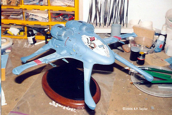
I gradually adjusted the trim line until it closely matched the contours of the main body, then I removed the forward area of the surround (leaving essentially a frame that exposes the clear bubble). I nested the clear bubble and surround together and with a Sharpie, transferred this shape to the plexiglas bubble. I carefully cut this area out (plus a sixteenth inch or so) then glued the clear bubble to the surround with plastic solvent. Because I wanted the canopy to be removable, I glued three small magnets to the inside of the canopy and drilled and glued corresponding steel pins into the main body. As a result of careful placement of the magnets, the canopy is self-registering. Finally, a few panel lines were scribed in, a couple of kit parts glued on and a half round styrene strip was applied not only to represent a canopy seal, but also to disguise any slight mismatch. I then masked off the clear area both inside and out to protect the plexiglas from primer and paint. Late Addition Just when I thought I was nearly done, I had another idea that I thought might add more visual interest to the Skimmer . Since it was now definitely a fighter, maybe I could add a couple of missiles or drop tanks to the underside of the wings. I never could decide which they were, but I added them anyway and they certainly gave it a more aggressive look. These were created in the same way that most of the rest of the Skimmer was made-carved renshape patterns and detailed vacuum form shells, while the wing mounts were made of styrene and plastruct channel. Final Finishing At this point I sprayed the Skimmer and its various subassemblies with a gray automotive primer, then began applying Nitrostan spot putty to any areas that required it. You may have noticed that this was done before the engines were attached as there were areas better dealt with without the engines getting in the way. With that done I finally glued the engines in place after first feeding the wires for the engine lights through the quarter inch hole on the underside. Final filling was done with more applications of Nitrostan and after another coat of primer; the Skimmer was ready for its base coat. The model was painted with Dupont Chromabase paints applied with a Badger automotive touch-up gun. I use this particular gun for the majority of my painting but I will occasionally break out the airbrush for the really fine or delicate stuff. Once the blue-gray basecoat was dry, I masked off and sprayed additional custom colors onto the main body and engines, red bands on the wings and a light gray for the interior. The dashboard and seat were painted and detailed, then epoxied in place. Next, custom graphics were applied, and sealed on with a matte finish. Weathering was kept to a minimum and was accomplished with black pastel streaking and some Model Masters steel to simulate paint chipping. A final light spray of matte lacquer sealed on the weathering effects and with that, the Skimmer was now complete. It did however require a display stand which I made of acrylic sheet affixed to an oak base. Before assembling the stand, a groove was milled into the acrylic into which the wires from the engine lights were laid. This groove was then filled in with quick-setting urethane resin, permanently embedding the wires, and when cured, it was sanded smooth and painted black. The Skimmer was mounted to the completed stand, with final wiring connections made beneath the base for a wall adapter that would provide power to the engine lights. The Skimmer was one of my entries in the Wonderfest 2005 Model Contest, where it was awarded Silver in the Vehicle/Mecha category. |
![]()
This page copyright © 2006 Starship Modeler™. First posted on 13 December 2006.
![[Please click to enlarge]](bp_skimmer/bp_skimmer_02.jpg)
![[Please click to enlarge]](bp_skimmer/bp_skimmer_05.jpg)

![[Please click to enlarge]](bp_skimmer/bp_skimmer_15.jpg)
![[Please click to enlarge]](bp_skimmer/bp_skimmer_20.jpg)
![[Please click to enlarge]](bp_skimmer/bp_skimmer_28b.jpg)
![[Please click to enlarge]](bp_skimmer/bp_skimmer_28c.jpg)