
|
By Jack Wendt - images & text © 1999
I call this the poor man's way of properly redoing the Space 1999 Eagle transporter. I have seen the after market kits, and they looked pretty good, but I was unwilling to part with the money. The only after market item I got were the decals from Jay Adan at Tangents (Ed. Note: No longer available). I had an old kit bought when it first came out about 20 some odd years ago, and had just received a new reissued one a couple of months ago. |
|
| Click on each picture for a larger view.
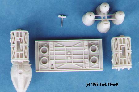
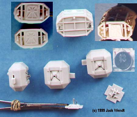
^ Detailed subassemblies before painting
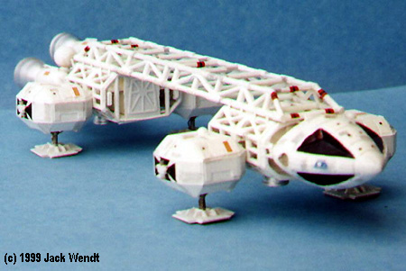
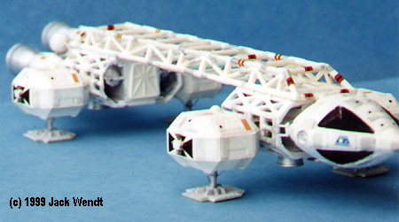
^ Three views of the finished "lab" eagle.
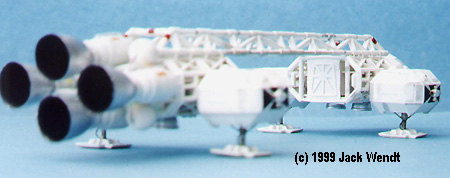
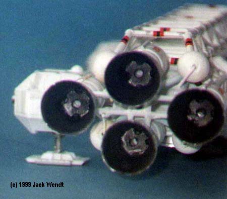
^ Engine bells. Note the inserts.
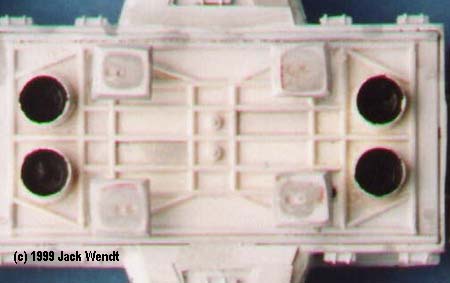
^ Underside of Lab Eagle. Note the repositioned "feet". |
I decided to start working on the old one that was poorly put together, but first I downloaded around 10MB of pictures from:
I chose to first build an Eagle with lab pod and the spine thrusters, and a standard Eagle. These are the basic parts I either purchased or had on stock. Now if you go out and buy all of this, it will almost be the cost of one the after market kits. You will have tons of left overs that you can use on future kits that offset the initial cost, however. You may also choose to use either thinner or thicker pieces of plastic from what I did, depending on how you study your reference photos. The two cages were the first thing I worked on (parts # 6, 7, 10, & 11). I drilled out the space between the girders. I then used a Dremel mototool to get more of the plastic out, finishing off with a sharp knife and several small files to clean up the corners. You want to do all this work before you start removing the top and bottom of the 4 pieces that make up the cages. Do not give up. You are looking at the work that you have done and are saying, "Hey this looks like crap". Trust me, you will be surprised at the final results; they will look better than you think, because of everything else that you do to this ship will distract from any errors. Also, since you will be removing the top and the bottom from the cages, you will be able to choose which side of the cages you want to be seen from the top. Using parts #8, & 9 you then place the carved-out cages temporarily on the end so you can cut a piece of plastic and recess it under the 2 side cages. Leaving about 1/8" on the sides of the cages, carve out the top and the bottom. Now is the time to choose which will be your top and bottom views, based on which one shows the fewest errors. Then (still using parts # 8, & 9), glue the replacement piece in the bottom and top of the cages. Now in the larger models this flat area did not go to both sides. They were supported by tubing, but to add strength in this kit I chose to simply use recessed sheet styrene to run across. Once that was done I built 2 rectangular boxes that are about the width of the doors in parts # 8 & 9. You now will use Q-tips as the tubing that runs across between the sides of the cages and the front and back of the cages. Please note that the Q-tip placement is different for the top and bottom of the cages, as well as rear and forward. Note the placement of the bottom 4 thrusters. As far as the rest of the detail you can put bits between the new passenger wall and outside of the cage, but you really can't see much describable detail when all is said and done. As far as the tops and bottoms, I use strip plastic, sequins, a doll's eye, etc., for the little do-hickeys. In the lab Eagle I completely rebuilt parts # 8 & 9 saving only the door, which is the wrong shape anyway. On the standard Eagle I trimmed out the areas that should be opened. This again will make your model stronger/simpler then scratch building this part. Do not glue on the thrusters until closer to the end of construction. Once satisfied with the cage, I proceeded to remove the back part of the command module from parts13 & 14 with a saw. Now if you compare the lab module Eagle and the standard Eagle you will see the 2 different ways I approached this problem. On the lab eagle I did as described above and added sheet styrene to build up the back of the command module, so it can be glued to the rectangular passenger area with in the front cage. In the regular Eagle I removed most of the area with a drill, Dremel, and files but left it attached at the clamping positions to the control module. The latter is heck of a lot easier and still esthetically pleasing. There are 2 thin strips of plastic for connecting the command module to the first cage, on either side. On the landing pods, I scored around the area that is to be removed in parts # 20, 28, 16, & 24. I then removed as much material from the inside with a Dremel, until I could cut though it from the outside. I then built up the inside with scrap plastic before drilling a hole for the new aluminum tubing. I used 2 thickness of tubing (see parts list below). I took thin piano wire and bent it in the shape of a "V", with a flat area on the bottom. This was glued to the bottom, now recessed, area of parts # 20, 28, 16, & 24. I also used a piece of wire in the shape of a "L" for the "shock absorber." You can see the proper way the pods join up with the Eagle and what portions of parts # 19, 27, 15, & 23, which are now glued to 20, 28, 16, & 24, need to be trimmed. Once this is done, you can go back to the cage sections and remove half of the rectangular box into which the completed pods insert, according to whether they are forward or rear position. Finally, remove the lip where the 4 small side thrusters are to be attached, over the black decal. The side thrusters go in the center on top of the black decals, but not the top of landing pods. I then reworked the landing pads, parts # 21, 29, 17, 25. I first drilled the hole in the exact center of where the plastic strut that I had removed was, and then reshaped the 4 cross braces for the landing pad. In other words it is not 4 cross-section equal distance ribs. It is 2 sets of equal distance ribs. Do not glue the pads to the pods until everything else is completed. The next section is the engine bells and cones. I removed the balls, parts # 35, & 36, and sanded as best I could on the older model. I routed out all sections of part # 12; however, the middle sections really don't need it as it is solid anyway. Just rout out the area that covers the edges of the rear cages. I used wooden beads for the new balls, added more Q-tips to replicate the tubing on the actual model, and used left over wire for the part that supports the balls. The tubing mounts on the nipples of part # 12, and attached at a inward angle near the center of part # 41. There are also 4 pieces of tubing that go straight from part # 12 to part # 41. All engine cones have a flat circular disk with semi circle cut out at 4 points and a center hole. I used a leather hole punch for this. |
|
The next section is the engine bells and cones. I removed the balls, parts # 35, & 36, and sanded as best I could on the older model. I routed out all sections of part # 12; however, the middle sections really don't need it as it is solid anyway. Just rout out the area that covers the edges of the rear cages. I used wooden beads for the new balls, added more Q-tips to replicate the tubing on the actual model, and used left over wire for the part that supports the balls. The tubing mounts on the nipples of part # 12, and attached at a inward angle near the center of part # 41. There are also 4 pieces of tubing that go straight from part # 12 to part # 41. All engine cones have a flat circular disk with semi circle cut out at 4 points and a center hole. I used a leather hole punch for this.
First, the feet that the pod rest on are molded in to the bottom of part # 4. This is the correct shape for the standard module, but the lab model has square, not rectangular pads. I tried to position this in the center of the area where the rectangular pads had been, but this did not leave enough room for the new thrusters that I made. The pads are simply square styrene with 2 ribs running on either side of the shaft/tubing/leg that goes up into the module. I now vacuformed a total of 6 new thruster for the bottom of the lab module. Using .20 or less thickness of plastic you can either use the existing bottom thrusters as the forms for vacing new thrusters, or you can mount any of the 4 thrusters with a dab of super glue on the end of a pencil in a vise. Then heat plastic over a candle until it sags and pull it over the form. As stated you need 6 if you plan to replace the inaccurate pod thrusters on the original supplied part # 4, and the additional thrusters for the actual lab section on the bottom. |
|
Now for the side of the center passenger module section. Fill in the windows in parts # 2, & 3 with scrap plastic, and cut plating to cover the windows. Using pictures of the studio model I traced out the shape of the lab modules and built them as best I could. There are 4 tanks mounted on both sides of the module and one on the top and the bottom of the lab section. This is solid styrene rod, Evergreen item 213. Take an armature out of any electrical motor (not in use), such as those cheap hobby motors, and curl the copper wire, several turns, around of the styrene rod. Cut a couple of curls off and attach to the rod to make it look like tank straps. The side thruster section to the lab pods turned out kind of crappy. It is supposed to be shaped like an inverted pyramid. I wound up filling the rectangle area with putty, and concaving it with my finger. Black sheet decal was cut and used in this rectangle, and resembles the black decal on the landing pods done earlier. The black decal covers the inaccuracy of where the side lab thrusters are located. I used round took picks to make the thruster cones, but you can use the business end of ink pens if you have 16 of the same type laying around. Of course if you have 32 ink pens you could replace all side thrusters. The plating on the lab pods were primarily Evergreen .20 sheet plastic. The door frame on each side was made by 2 strands of wire used in telephone wiring, bent, and then glued. The paneling for the doors is half round rod # 242. I used styrene strip along the top seam of the passenger module, because when I broke it apart the original 20 year old model, it required too much sanding to rebuild, hence the strip. The only modification to the spine, part # 1, was to use Q-tips for the bottom runners across the width and in line with the top cross bars. Next I built the spine booster. The engine cones were recast by vacing 2 new engines from the ones supplied for the rear. Again use the thinnest sheet plastic you can find. To make sure heat did not harm the cones, I stuffed playdough into the inside, and had no problems with this method. The 4 tanks measure about 1 & � " and I used Evergreen #232 which is 3/8" tubing. The 2 top tanks measure 1 & 1/8" and I used Evergreen 228 which is �" tubing. The rust colored tank is the same tubing as the four, only shorter at �". I used part of the now replaced balls, parts # 35 & 36, from the engine section to make the ends of the other 6 tanks. Check around the house, you may find enough tubing in the right size from various ink pens. The main support structure that the tanks are attached to is just sheet plastic with added do-hickeys. The 2 gray pancake-shaped tanks that can barely be seen between the 2 smaller top tanks, were made from a pill/tablet medication blister pack. To make the parts go together, you really are supposed to remove about 3/16" from the length of the spine, part # 1. I did not because I did not want to lose the strength of the spine. If you choose to use parts #8, & 9, because of the doors, then you can choose whether to leave the 4 bumps that make contact with parts # 2 & 3 on the passenger module. On the lab they were not used, and on the standard they were left on, but sanded down some. I did not attach either the spine booster or the lab module to the transporter with glue. I may build the cargo version, and I don't intend to build another complete Eagle just for the cargo addition. The model was painted with Testors flat white, and the gray is Light Ghost Gray that was diluted. The engine cones were painted with Humbrol #11., with flat black for the glare shields. I used a lead pencil to put some stripes on some of the wire used in the engine section. Checkered decals was used on the booster. There is actually supposed to be 2 sizes of checkers, the smaller being used on the small tanks. I only had one size available. I like the decal sheet that I got from Jay Adan. There are enough decals for about 3 Eagles. I did find that one end kept tearing for the black decal that goes on the 4 landing pods. No matter, I simply used some left over black striping decals for the ends that tore. The decal sheet is still a great value for correcting the inaccuracies of the kit-supplied decals. Coat the black decal center of the landing pods and lab module with a generous coat of Future and let dry. I glued the side thrusters for the landing pods, and lab pod on to the decal using white glue. It was a lot of fun trying to get not 4 legs, but 8 legs to all sit properly. Not counting the cost of the actual model kits, I spent less than $20 in material as some I had from previous endeavors, and of course what I did purchase can be used on future models. |
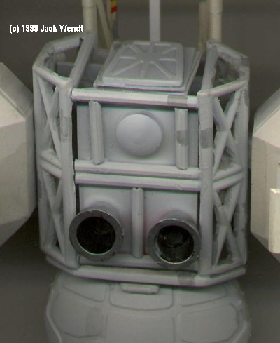
^ Three views showing the detail added to the cage sections.
^Two close-up views of the reworked and detailed engines sections. |
| |
|
|
Materials Used: Evergreen product # 's
|
Miscellaneous:
|
![]()
Go back up | Other Sci-Fi Spacecraft Page | Starship Modeler Home | Site Map | Feedback
This page copyright © 1999 - 2016 Starship Modeler™.
Last updated on 31 May 2016.
![[The two ships]](jw_1999_3.jpg)
![[Finished subassemblies]](jw_1999_11.jpg)
![[Lab-side]](jw_1999_12.jpg)
![[Lab-oblique]](jw_1999_13.jpg)
![[Lab-without lab]](jw_1999_14.jpg)
![[Rear View]](jw_1999_16.jpg)
![[Underside]](jw_1999_18.jpg)
![[Twins]](jw_1999_17.jpg)


