
By E. James Small - images & text © 2001
|
|
|
|
Two models were built at 22" in length, the first being featured in most of both seasons, and the second one was seen only briefly during the end of the second season. This kit attempts to duplicate the #1 and #3 44" studio model at approximately 23 inches in length. I was commissioned to build this kit for a customer, so I made a few modifications to the original kit as well, to make it a bit more accurate, easier to build and more "shippable".
First Impressions: Upon opening the box, I was confronted with a series of bagged small parts and some loose large parts all packed among those clingy foam peanuts. A set of Alpha Moonbase crest decals are also included, which appear quite accurate. They appear to be the ALPS printed type. A set of very crude instructions are also included, but they are really inadequate to build this model unless you are already quite familiar with how an Eagle goes together. They are a rough guide at best so don't expect these instructions to take you by the hand as you waltz through this project. You need to use a lot of common sense to figure out some of the parts locations, as the drawings that show many parts are almost too crude to even tell what they are. It is replete with "updates" that were designed to go along with the kit's development but there are also sections that do not reflect changes in the kit as well, meaning that the instructions were not updated as often as necessary. In order to build this kit, it would be a big help if you are familiar with the intricacies of an Eagle to begin with, but then, if you're laying out $300+ for it then you're probably already a major fan and know the model fairly well anyway, and aren't just buying it on a whim. |
|
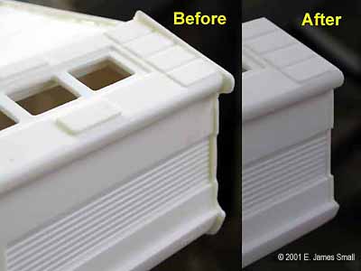
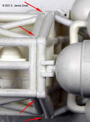
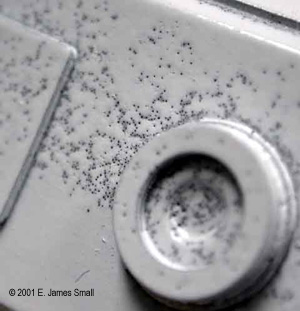
The parts are quite well cast, but there are "pits" and dents in many areas that are the result of not de-gassing the rubber before pouring it over the master. Heat from the setting resin expands the air bubbles close to the surface and causes tiny dents in the cast part. Also, there are a tremendous number of tiny bubbles on the surface, most likely a result of "whipping" the resin as it's mixed. Mostly, these pits and bubbles will all but disappear when the model is painted properly and weathered (I had the same problem with my own kits before I built my vacuum chamber), otherwise, it'll take a lot of filling and sanding to remove them.
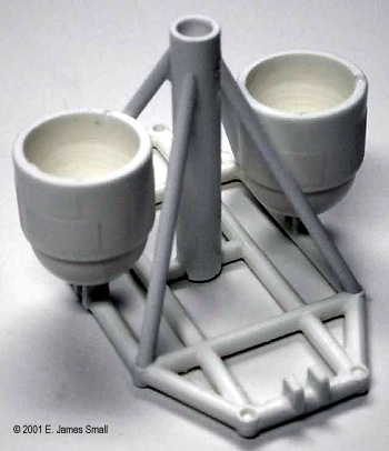
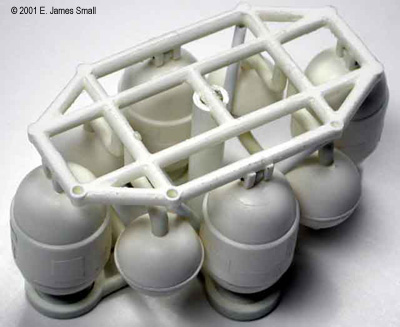
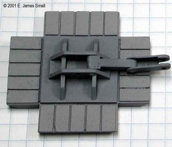
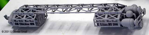
Preparing to build: The first thing I did was spend an hour or so going over the kit and familiarizing myself with the parts and their location. The instructions were barely consulted, as they weren't much of a help anyway. I've built a number of Eagles in smaller scale from, and modified from, various kits in my day, and have spent literally years studying my favourite spaceship, so it wasn't a chore to figure out where everything went. I began cleaning up some of the flash on the parts using files and sandpaper. Large holes or gaps were given a shot of CA accelerator, then filled with drops of thick CA which was then sanded smooth. Construction begins: As you read this construction review, it's important to note that the model was not necessarily built in the order written here. As I studied and built this model I found it necessary to jump all over the place to figure everything out. For example, some modifications were done even after the model was painted, so that is why some of the pictures show parts being worked on with paint on them, even though this writing indicates otherwise. Engine section: I began with the part I thought would be the most fun to build to get me into the spirit of the project (not that I really needed any help!), so I started with the engine cluster. I was right! This section was a lot of fun to build! After cleaning up the parts and test fitting the components together, I drilled tiny holes into the sections of the frame where the front of the cylindrical engines connect, and also corresponding holes into the little nubs on the engines as well. Pins were inserted into these holes to hold them together. This is similar to the way the original FX model is made too! This allowed me some flexibility to fit the other parts into place. I added a plastic tube to the centre of the construct and the triangular A-frame. These parts are not included in the kit, but ARE on the studio models. These parts also add a lot of strength to the section as well, and so I highly recommend you make this modification to your kit too. That little A-frame came in real handy as a rod mount for painting the model too! Incidentally, using it as a model mount while filming was precisely why that structure was installed onto the original studio models as well. The rest of the engine bits were added around this frame and topped off with the cross section. Other than a cursory look, the instructions were not rigidly followed here, because it results in a less accurate construction. You cannot easily mount the bells into place as indicated in the instructions, because they seem say to mount the screws into the bells from the BACK of the cross piece, which presents a real problem if you want to paint the engine section as a unit. You'd have to paint it separately and glue the cross and bells on after all painting was done. Also, I did not glue the back of the pipe section that attaches the Eagle's "testicles" (balls) together to the cross piece as shown in the instructions, since this is inaccurate and looks awkward. Instead I assembled the balls to these pipes and glued the pipes to the main frame. The balls also rest against the added a-frame too, so a drop of glue was added there for extra strength. Thin and medium cyanoacrylate was used to hold everything together.
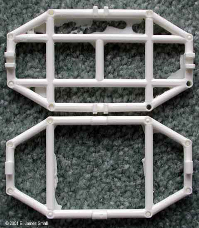
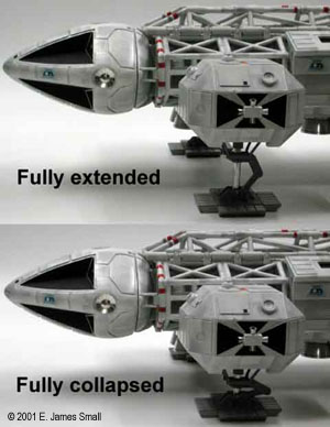
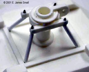
Passenger Pod: Although this piece looks like it would be the easiest part to make, it has turned out to be one of the most difficult because of the poor parts fit. For example, I had to use a belt sander to remove at least a quarter of an inch from the edges of the roof where the parts fit together. If you just glue the parts together without this necessary trimming, the side walls will not be parallel (when viewed from the end) when the floor is put in place. The parts were sanded until there was no side-to-side play when the spine was placed on top of the roof. There is a significant amount of trimming on all parts required to get the ends of the pod to fit into place. There is also a gap that needs to be filled between the floor and the pod's ends as well. Care must be taken to glue the parts together without introducing a permanent warp into the structure. The passenger pod was also modified to accept the wiring, batteries and switch necessary to illuminate the cockpit. Wiring for the cockpit exits the pod via a detachable connector and through the body frame section into the nosecone. The custom-made aluminum VTOL bells and the leg struts were screwed into place so they could be removed for painting and replaced at will. Body Frames: Spine: The spine, as mentioned earlier, was warped significantly into an upward curve because of the imbalance between the lower and upper longerons. This ended up being less of a problem than I originally thought however, because of the results of final assembly. More about this later though. I used a heat gun to "un-warp" the spine and get it ready for assembly after cleaning up all the flash. I have to give the manufacturers a lot of credit for this part, because if there's anything about this model that's difficult to cast, it would be the spine. There was a lot of flash and air bubbles to clean up, but overall, it was a piece that was well done considering it's complexity. The kit comes with a length of butyrate tubing (a bit oversized though) for the cross members for the frame's underside, but the totally useless instructions don't even mention this operation. My aforementioned familiarity with the Eagle came into play here again, so I cut up the tube to make these cross pieces. There was not enough of the material included in the kit, so I pulled some out of my own stock to finish the job. Shoulder Pods and landing gear: This part of the model is the most complex and time consuming to make because of the functional oleo struts, but it's worth the extra effort. When done, the landing gear looks mostly like, and behaves exactly like the ones on the original 44" studio model. After cleaning up all the parts, I had to determine the correct geometry of the leg components. The first thing I did was consult my information to determine the correct proportions of all the parts. The instructions show a drawing at actual size of the oleo struts and the holes that you need to drill into them to make the unit "work" properly but nowhere in the instructions are you informed of this. I figured the dimensions out for myself using the extensive reference I have and then discovered that this task has in fact already been done for you. You can use the actual-sized drawings to figure out where to drill the holes in the aluminum tube supplied, which was cut evenly into four pieces, then slip on a cotter pin, a cup and the spring. The little trapezoidal frames under the pods were made from some 1/16th inch plastic coated wire that I had. The kit comes with some thinner plastic coated wire, but it is too thin to look right. The oleo strut support at the bottom of this assembly was carefully cleaned up and holes drilled to accept the wire. Looking at this picture will describe most of how this assembly was done better than words can.
The feet were pretty straightforward, but the oleo strut stabilizers needed to be trimmed and modified to work properly. They need to be loose enough to move easily, but not overly floppy. The top channel piece of the stabilizer arms was shortened considerably, since they are actually a bit too long and don't allow the assembly to "fold" properly when the model is at rest. Holes were drilled to accept hinge pins on all joints. The oleo stabilizer parts were pinned to the feet and painted as a unit. The feet would be permanently attached to the oleo strut and pinned in place after the model was painted. Nosecone:
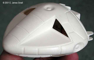
Another important thing I did was to add a significant amount of weight to the nosecone. Because the engine cluster with the aluminum bells weighs so much more than the nose, I knew that would present a problem with the model balancing properly on it's spring loaded landing gear. I weighed the two opposing assemblies and put the difference in the form of lead fishing sinkers into the hollow front end of the nose and poured resin into the nose to hold the lead pellets in place. Pre-painting assembly: I wanted to put some of the parts together to be painted as a unit, mainly the frame sections, spine, engine section (sans bells) and the back section of the nosecone. These were assembled with CA and painted as a unit. I also added some little styrene "clamps" to simulate the ones on the original that hold the frames to the spine. These were not included in the kit. The Passenger Pod , the shoulder pods and the nosecone were all assembled as separate units as well ready for painting. Little details like the passenger pod legs and the shoulder pod attitude jets were left off and painted separately. Painting and detailing: I began by spraying the entire model with grey primer. This allows you to discover any flaws that you may have missed while assembling the model. I just about fell over backwards when I saw what cropped up. On many areas, particularly on a fair sized section of some of the shoulder pods there were literally thousands of tiny, almost microscopic, holes caused by resin that had "foamed" somewhat when it was poured into the mold. How to fix this problem? They stuck out like a sore thumb and looked pretty awful! I tried to spray some of the white topcoat over the area but that only made things worse. I thought it would take forever to try to sand and fill all these pinpricks, so I loaded the white finish coat (automotive laquer) into the airbrush and blasted bursts of the white paint at very close range onto the affected area. It worked! The paint was blown into the holes effectively filling them up and covering them over. Excess paint was quickly blown about to smooth it out. When it dried, the holes were all but invisible. The entire model was given this treatment where necessary, then given a finish coat of white laquer with the airbrush. It should be mentioned here that painting the assembled frames as a unit here worked to an advantage. One would think that the paint would not reach the inner boxes very well under the framework, and that is true. The trick is to make sure those boxes are completely covered in primer from the airbrush by blasting short spurts between the frame bars, then when dusting on the white paint you end up deliberately not painting the detailed boxes with as harsh a coat, thereby introducing what could best be described as ready-made weathering. It enhances the scale of the shadows and covers a lot of flaws too! I like this technique better than "drybrushing" because it's more realistic (at least in this case) and a helluva lot easier to do! After the model was sprayed white, a quick "wash" was given to the model with heavily diluted grey paint (Tamiya acrylic paint diluted with alcohol) thinned down to the point that it looks like dirty water. The airbrush was loaded with this wash then sprayed at high volume over the entire surface of the parts, a bit at a time, wiping the excess off with a rag as I went, before the solution could dry. This leaves the "dirt" embedded in various nooks and crannies. When this was dry I cut out a piece of cardboard into an "L" shape and began spraying gray primer with the airbrush all over the model, using the card as a hard edge to create "paneling" detail. This is precisely the way the studio models were sometimes done I might add, and it's a very fast and effective way to create mechanical looking weathering. When you recognize this technique, you can see how it was used all over most of the models seen on Space 1999! As a final touch, to tone down the harsh weathering and give some uniformity to the model, I lightly dusted on an additional coat of white laquer with the airbrush. The aluminum engine bells were sprayed with a little flat black shot into their centres of the bottom VTOL rockets and on the baffles on the back of the main bells. After the weathering was completed I grabbed a paintbrush and cut in the details like the black cross areas on the shoulder pods and the windows and other details. The striping on the frames and shoulder pods were done with pinstripe tape and painted paper labels, again similar to the way the studio models were done. The silver sensor dishes on the nosecone were covered in Bare Metal Foil and a knife was then used to delineate the gore patterns. Although the decals that come with the kit are quite accurate, they aren't as good as the ones offered by Chris Trice, so I opted to use a set of his. Final assembly: After all the painting was done I began screwing everything together. I wanted to use screws as much as possible to permit disassembly if needed. The only thing I glued on at this point were the little attitude thrusters on the shoulder pods. The nosecone, Shoulder Pod halves, Shoulder Pods, VTOL thrusters, Passenger Pod bottom, Passenger Pod, Passenger Pod legs, and main rear engine bells were all screwed into place. Conclusion: Much like the original studio models, this kit builds into a very nice "arm's length" model, as I call it, meaning that it'll look really great sitting on a desk or shelf, but don't get too close to scrutinize it. It would take a tremendous amount of work to make this model suitable for close scrutiny or contest-winning condition. It can be done, but at a great expenditure of time in re-working ill-fitting parts and a lot of filling and sanding to remove the thousands of tiny surface flaws such as dents and bubbles. I think it's important to remember though, that the studio models themselves were built to a lower standard in some cases. This kit is probably done to a higher standard than, say, the original 22" studio model and is slightly more detailed, especially when you consider the functional sprung landing gear which only the 44" studio models had. Is this kit worth the $300 plus taxes and shipping that it costs? Well, only you can answer that question. If you have above average modeling skills, you like the way the model looks in the pictures shown and you are willing to pay the money to get a large Eagle model that goes together a lot faster than scratch building one, then the answer would be a resounding "yes". However, if you expect to get a very ACCURATE model with injection plastic quality for that kind of money then your dream kit is yet to be produced. Having said that though, to my knowledge this is still the best Eagle kit for the money that is currently being made and I recommend it to anyone who wants a really great model of this classic ship without having to build one from scratch! Hits: Nice large size, looks good when finished, good quality material, relatively(!) quick to build if not modified, makes an impressive display piece. Good attempt at kitting a difficult subject. Best Eagle kit for the price known currently to be available as of this writing. Misses: Should be a lot more accurate for the price, especially given the vast amounts of data available publicly today. Parts fit poor in places. Lots of tiny air bubbles and dents on many surfaces. Poor instructions. Should be better quality for the price. Click here to read John Lester's in-box preview of this kit. |
|
|
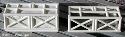
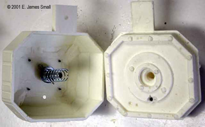
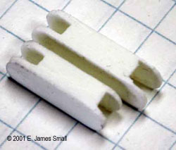
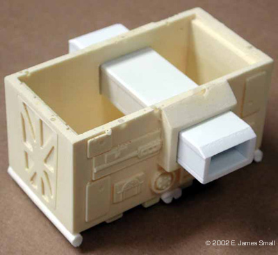
Addendum: First off, this kit has some parts that are cast differently than the first one I built. The nose cone was in seven parts (top and bottom front halves plus the four sensor dishes) instead of just two. Although the fit of the two front halves is very sloppy making the paneling detail on the side suffer, the four dishes which were cast into the nose cone on the first model (the side ones were sanded down into an elliptical shape which looked awful!) can be made to fit much better on this version, and allow for painting or covering in Bare Metal Foil independently. I also made improvements to the lighting system by building a box onto the back of the nose cone which contains the batteries for the two "grain of wheat" bulbs inside the cockpit. The switch is located underneath this little box. The battery box also acts as a "plug" to slide into a similarly prepared receptacle in the front of the companionway box structure inside the frame. To turn the switch on or off, you simply slide the nose cone out slightly and then slide it back in. This keeps the switch hidden from view as well as keeping the wiring and fiddling to a minimum. Another thing I did was improve the supporting structure on the companionway boxes, so I ignored the four small secondary receptacles that get glued into the side of them, and instead opted to cut the hollowed areas on the sides of the boxes out completely and install channels made of thick styrene plastic in their place which carried all the way through from one side to the other. This allows for a much stronger and more stable construction that eliminates the possibility of the pods sagging over time due to warping of the resin boxes. This much stronger design also more closely resembles the way the original studio models were built. The shoulder pod's top sections on this newer model are more hollow with a stubby central cylindrical section inside. This decreases weight slightly and allows for the replacement of the plug-in tabs with longer, stronger wooden ones. I removed the resin tabs on each of the four shoulder pod sections and replaced them with parts made from MDF (Medium Density Fiberboard). These were anchored to the stubby central columns in the top sections. I then drilled a hole into the central column and added a small tube to help guide the landing gear oleo strut and spring. The tube's inside diameter is slightly greater than the strut, but the spring also fits over the tube, providing much greater stability to the construction. |
![]()
This page copyright © 2001-2 Starship Modeler™. Last updated on 7 March 2002.
![[Click to enlarge]](js_rueagle_Fin1.JPG)
![[Click to enlarge]](js_rueagle_Fin2.JPG)
![[Click to enlarge]](js_rueagle_Fin3.JPG)
![[Click to enlarge]](js_rueagle_Fin4.JPG)
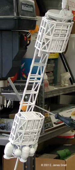
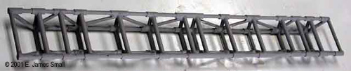
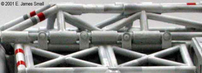
![[Permanence]](js_rueagle_Pp5.JPG) The spine, the largest single part of the model, had a significant warp to it. Heating the part with a hair dryer and flexing it back into shape helps, but this does not seem to be a permanent fix, as over time, the warp reappears. The problem is this: There are two reinforcing steel rods running the length of the spine embedded in the resin making up the two bottom longerons. The top two longerons do not contain these steel rods, therefore an imbalance takes place. When resin cures, it shrinks ever so slightly, but the steel rods on the bottom stop the resin in this area from shrinking as much, so with the top longerons free to shrink they introduce a bend into the part. The obvious way to fix this problem is for the manufacturer to place the metal rods into the top longerons as well. However, all this is pretty much academic, since I discovered that as I built the model, it became apparent that the spine is not really rigid enough to support the model without the passenger pod mounted in place. The pod, as shown in the instructions, is put in place with screws and must become a "permanent" part of the model (left). It is not really removable as it was with the studio models, as it provides most of the model's structural strength throughout it's length.
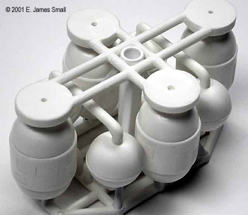
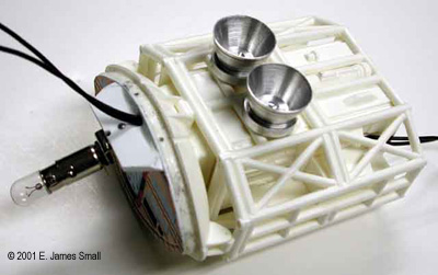
The spine, the largest single part of the model, had a significant warp to it. Heating the part with a hair dryer and flexing it back into shape helps, but this does not seem to be a permanent fix, as over time, the warp reappears. The problem is this: There are two reinforcing steel rods running the length of the spine embedded in the resin making up the two bottom longerons. The top two longerons do not contain these steel rods, therefore an imbalance takes place. When resin cures, it shrinks ever so slightly, but the steel rods on the bottom stop the resin in this area from shrinking as much, so with the top longerons free to shrink they introduce a bend into the part. The obvious way to fix this problem is for the manufacturer to place the metal rods into the top longerons as well. However, all this is pretty much academic, since I discovered that as I built the model, it became apparent that the spine is not really rigid enough to support the model without the passenger pod mounted in place. The pod, as shown in the instructions, is put in place with screws and must become a "permanent" part of the model (left). It is not really removable as it was with the studio models, as it provides most of the model's structural strength throughout it's length.![[Engine bell replacements]](js_rueagle_EC4.JPG) The finished section was then ready to accept paint (but I didn't paint it yet). I tossed the resin engine bells that come with the kit and used a set of replacement aluminum bells, made by my machinist Mike Reader, with new resin baffles for the inside of these bells. The new bells will be screwed into place after painting the model.
The finished section was then ready to accept paint (but I didn't paint it yet). I tossed the resin engine bells that come with the kit and used a set of replacement aluminum bells, made by my machinist Mike Reader, with new resin baffles for the inside of these bells. The new bells will be screwed into place after painting the model.![[Click to enlarge]](js_rueagle_Bf2.JPG)
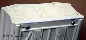
![[Mods to the pods]](js_rueagle_SP4.JPG) The modifications I made to these assemblies were the most extensive in the kit. The first thing I did was to use a long screw, (included in the kit for an unknown reason. Perhaps these screws were to be used to fasten the engine bells to the ship? The instructions don't say) to hold the
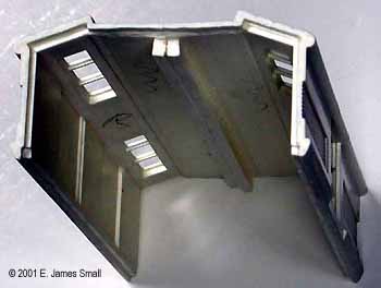
The modifications I made to these assemblies were the most extensive in the kit. The first thing I did was to use a long screw, (included in the kit for an unknown reason. Perhaps these screws were to be used to fasten the engine bells to the ship? The instructions don't say) to hold the ![[Lit up]](js_rueagle_NC4.JPG) The cockpit section was going to be lit, so I had to
The cockpit section was going to be lit, so I had to ![[Cockpit wall]](js_rueagle_Nc3.JPG)
![[Click to enlarge]](js_rueagle_New6.JPG)